Serial Peripheral Interface (SPI)
Serial Peripheral Interface (SPI) is an interface bus commonly used to send data between Microcontrollers and small peripherals such as shift registers, sensors, and SD cards.
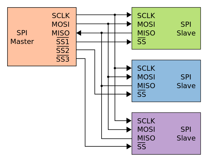
It uses separate clock and data lines, along with a select line to choose the device you wish to talk to.
The SPI bus specifies 4 logic signals:
- SCLK: Serial Clock (output from master)
- MOSI: Master Out Slave In (data output from master)
- MISO: Master In Slave Out (data output from slave)
- CS /SS: Chip/Slave Select (often active low, output from master to indicate that data is being sent)
Note: There is no standard for naming, sometimes you will see these with other names

Multiple Slaves

How It Actually Works
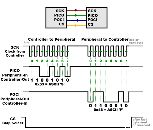
At each clock transition, there is transmission of data. Register?
SPI vs. I2C?
I2C is half-duplex communication and SPI is full-duplex communication. So SPI is a lot faster.
Notes from using with esp-idf
Use a polling transaction or an interrupt transaction? Both work
Let’s say you want to read a single byte from the sensor, your tx still needs to be 2 bytes…
- This is because you are receiving during the second clock cycle

Looking at this image, PICO sends data from tx_data[0]. However, it needs to keep going with tx_data[1]). This is the period during which the rx data is being sent.
Even if we only need to read a single byte from the sensor, we need to send the register address (with the read bit set) and then reading back one byte of data. Thus, it’s actually a 2-byte transaction:
- First byte: The register address with the read bit set.
- Second byte: A dummy byte sent out while the SPI clock runs so that the sensor can return the requested data.
https://invensense.tdk.com/wp-content/uploads/2021/07/DS-000451-ICM-42670-P-v1.0.pdf
- See SPI interface section