Synchronous Circuit Design
Goal: Given a verbal description of the operation that a circuit must perform, come up with a circuit implementation.
For Multiplexers, you just need to use Multiplexers, you just need to use Shannon’s Expansion and it’s pretty straightforward.
We use Flip-Flops to do synchronous circuit design.
Steps
I watched some Neso videos and I get the intuition. Added some commentary to the screenshots.
Step 1: Draw the State Table (Optional: Do State Reduction to reduce final number of Flip-Flops)
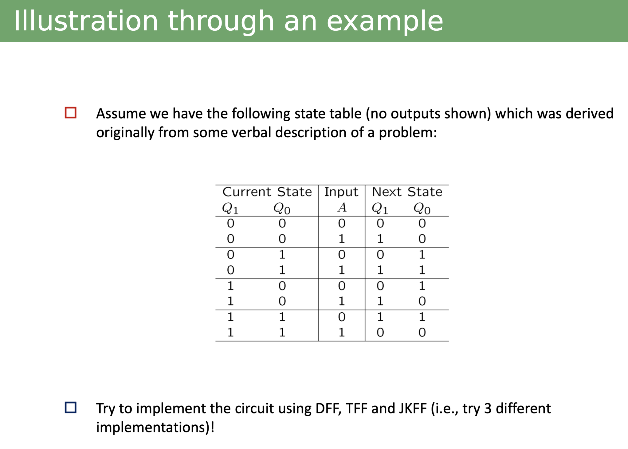
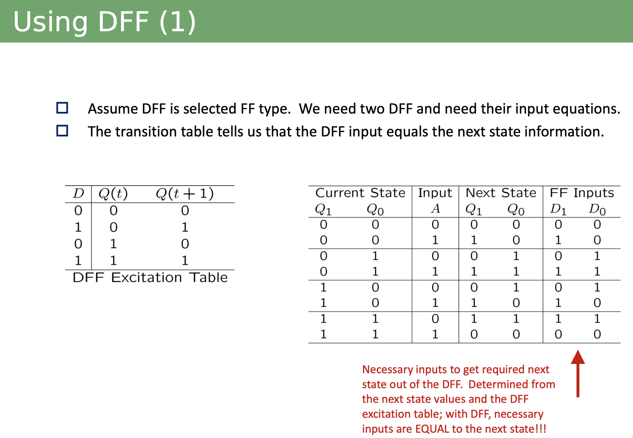
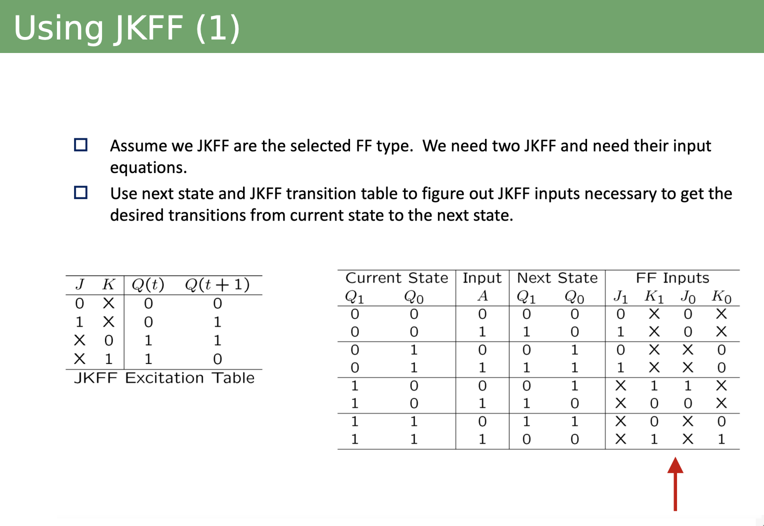
Step 2: Choose the flip-flop and draw it’s Excitation Table. The DFF is the easiest.
Then, use the excitation table as a reference to fill a new column for the FF Inputs on the State Table. This column tells us what FF inputs are required to go from current state value to the next state value.
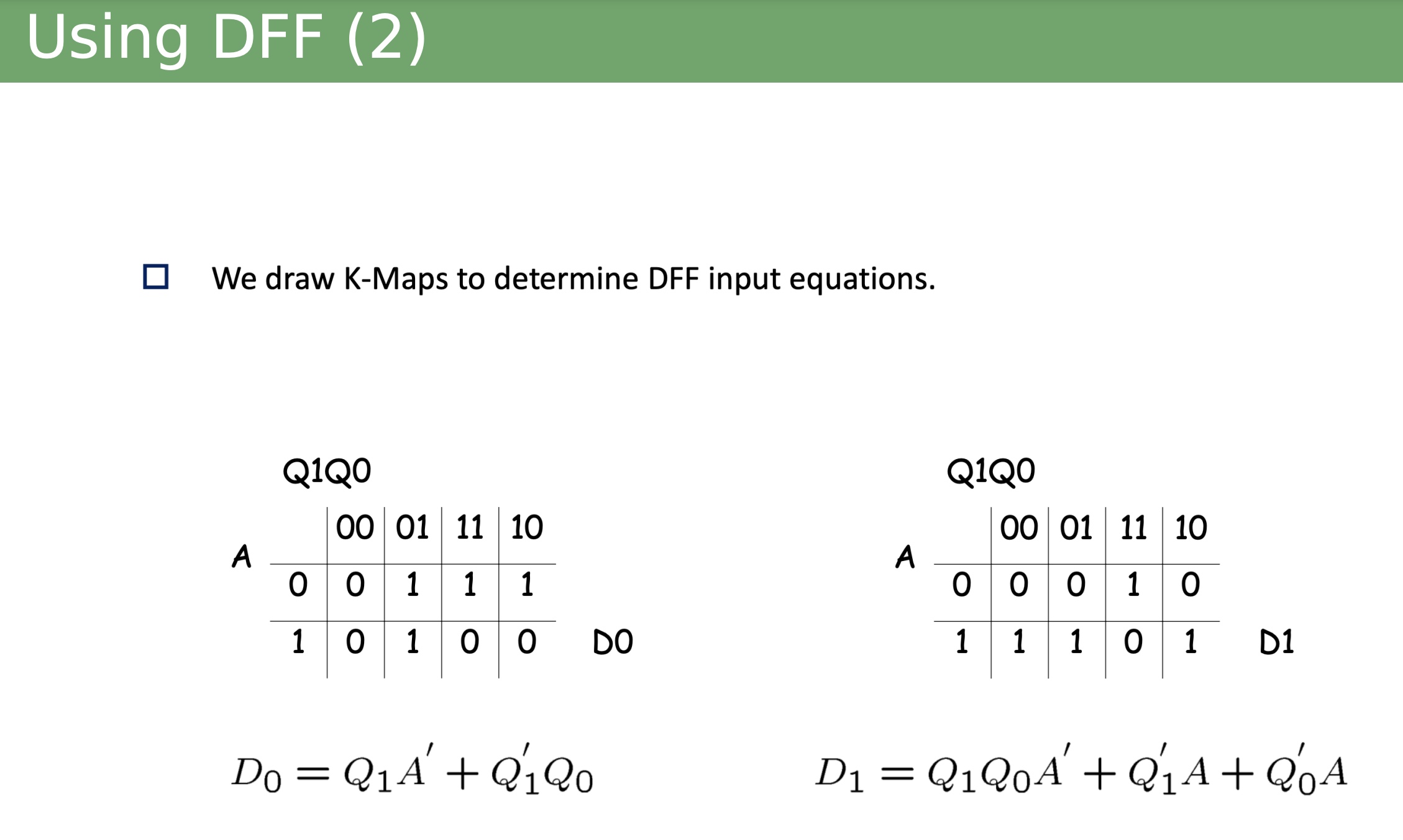
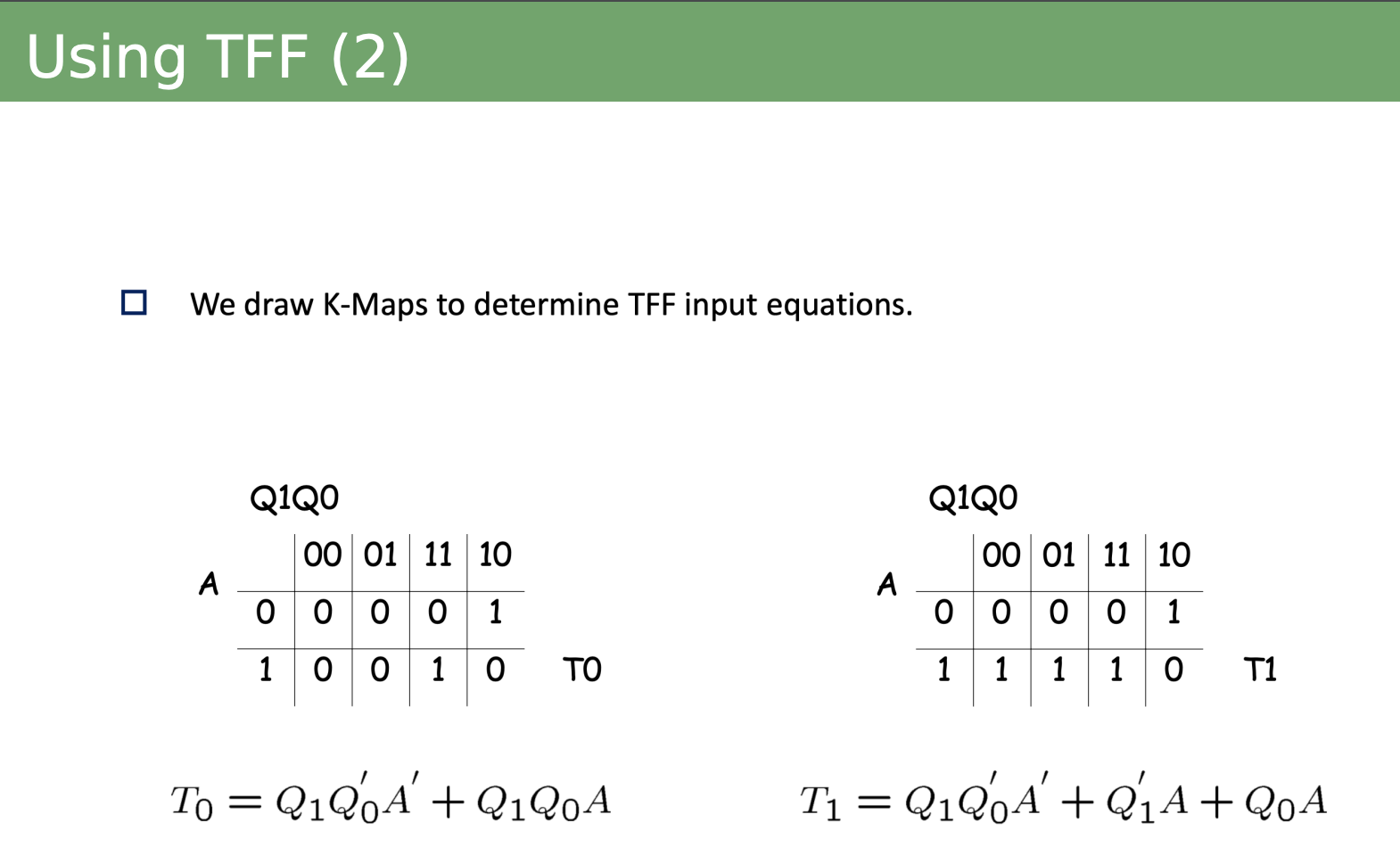
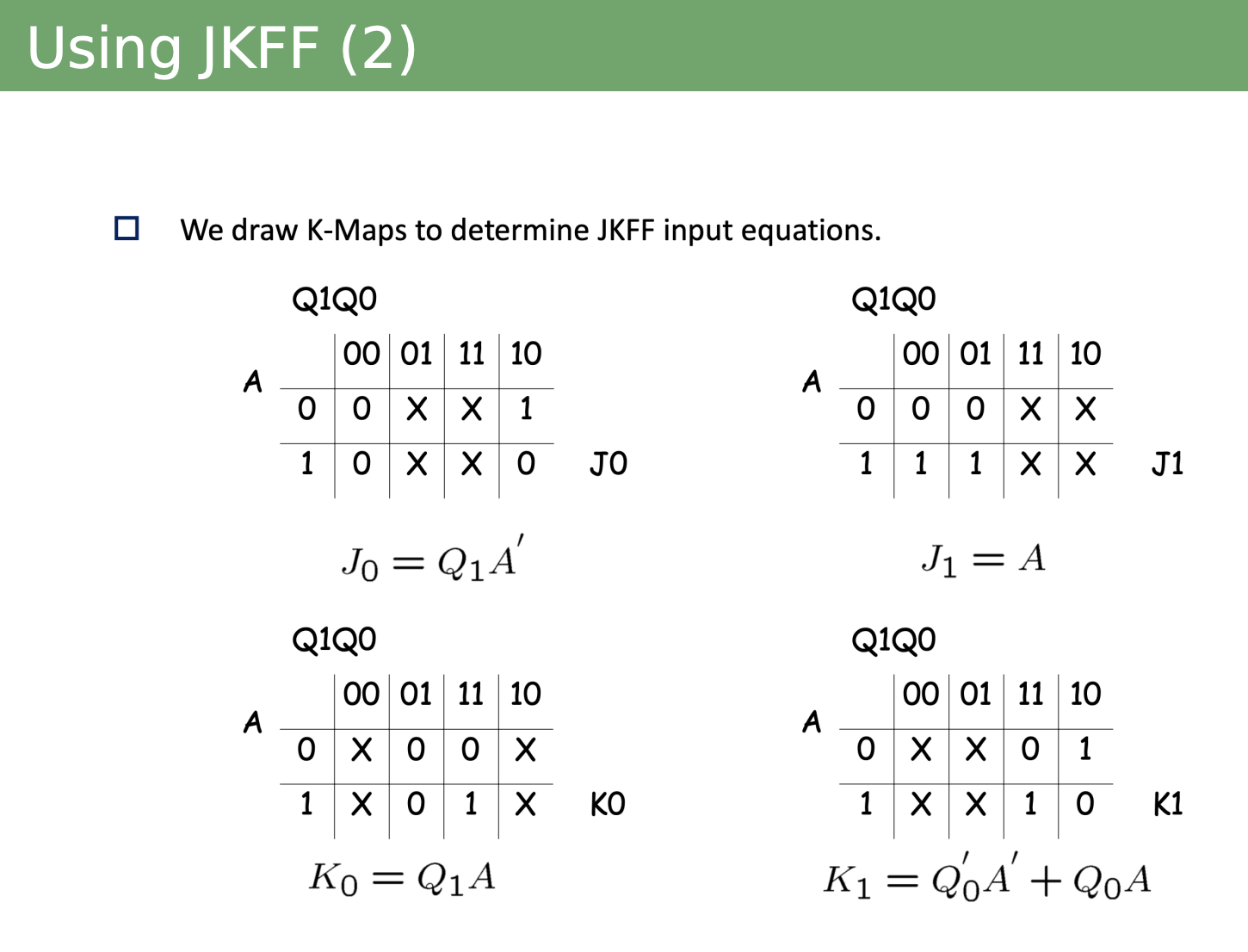
Step 3: Use a K-map to get the equation for each Flip-Flop.
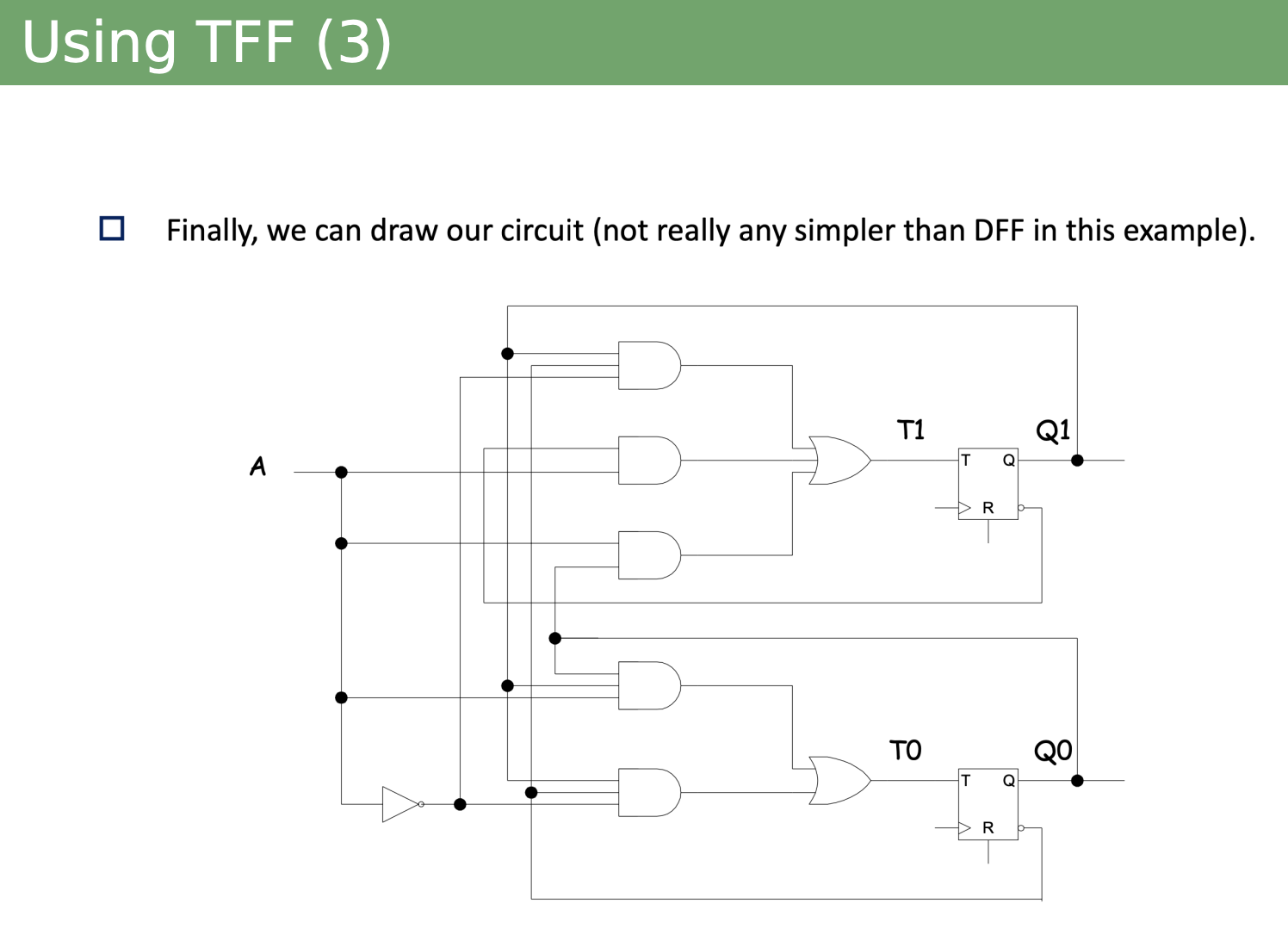
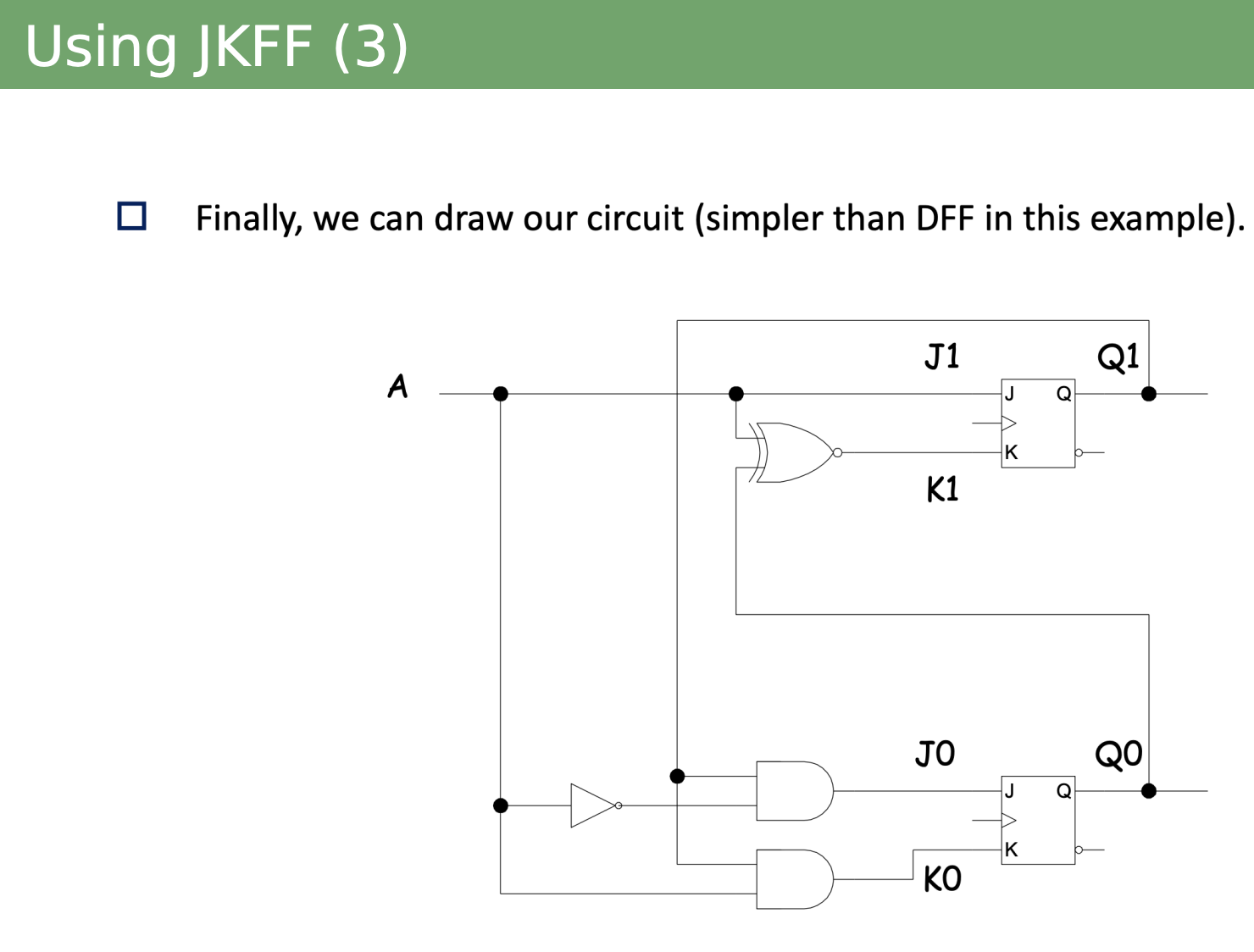
Step 4: Draw the circuit based on those FF equations.

Step 5: Not shown but usually there is an output for each state transition. The equation is usually given and easy, so just draw that on the final circuit.
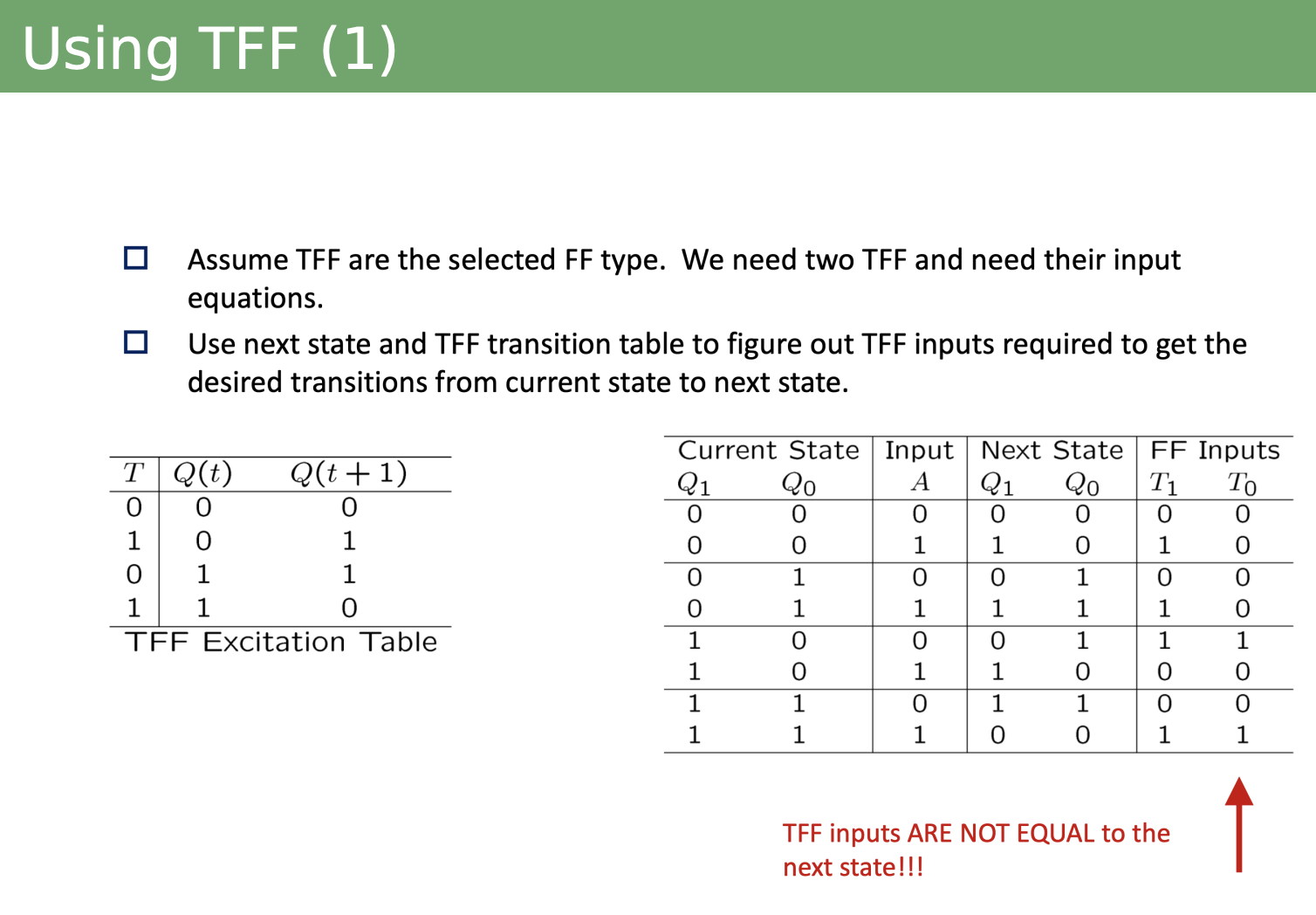
TFF Example
DFF is easy because they are just equal to the next state. But this is not the case with TFF!! We do the same steps, but the KMaps will be different.
JK-FF Design Example
For JK-FF, we double the number of Kmaps we need, since each FF has two inputs J and K (instead of just one like DFF and TFF).
Related
- Synchronous Circuit Analysis (essentially the reverse)
- Asynchronous Circuit Design