Flip-Flop (FF)
We wish to have storage elements that the change of their state is controlled under precise timing instances - clock edges.
Flip-flops are edge-triggered. See Clock
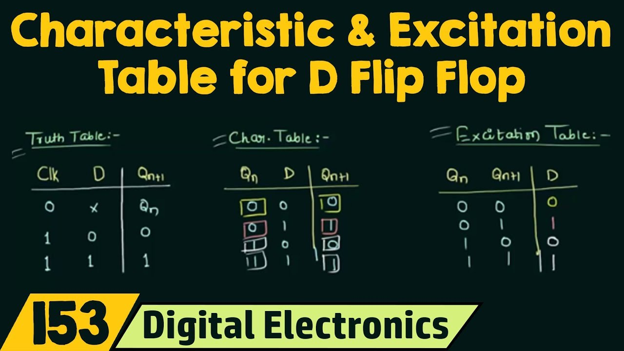
Tables
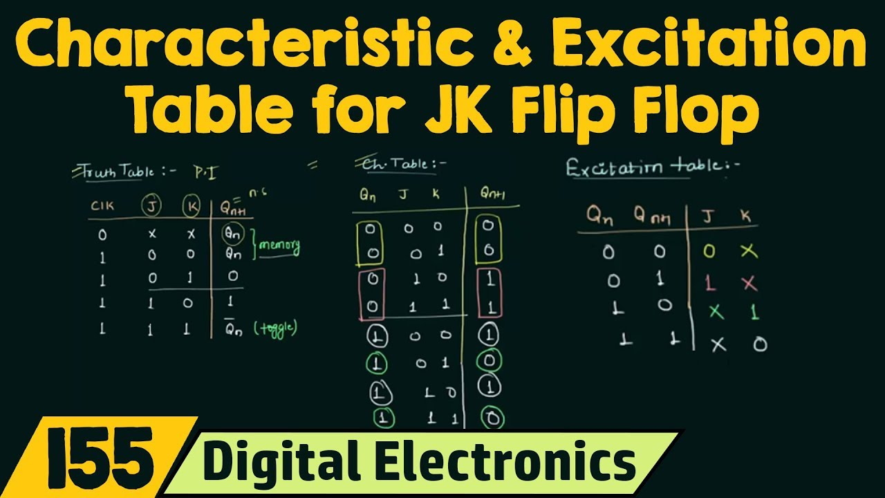
Truth Table: A Truth table shows how a logic circuits output responds to various combination of inputs. Characteristic Table: it defines the next state of flip-flop in terms of flip-flop input and current state. Excitation Table: it defines the flip-flop input variable as function of the current state and next state.
Edge-Triggering
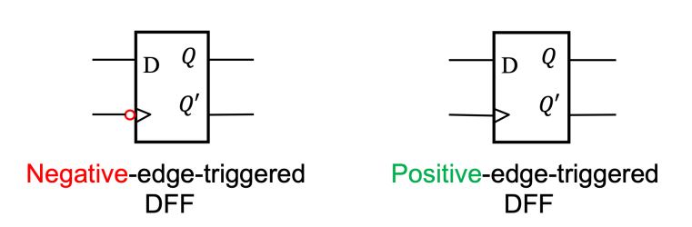
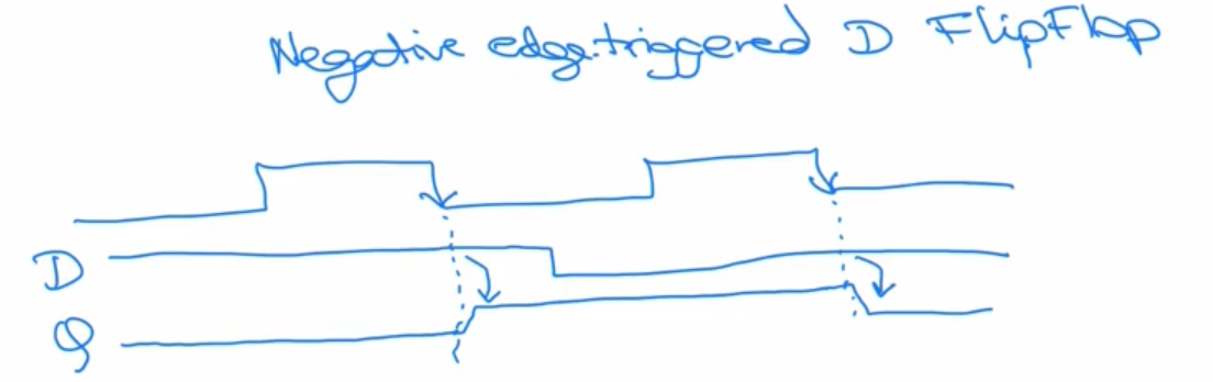
From ECE222, the teacher explained how when it’s negative edge-triggered, it means that the flipflop may or may not change on the negative edge.
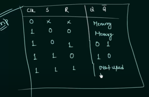
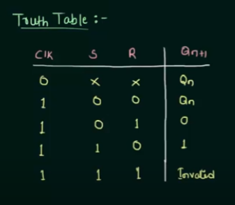
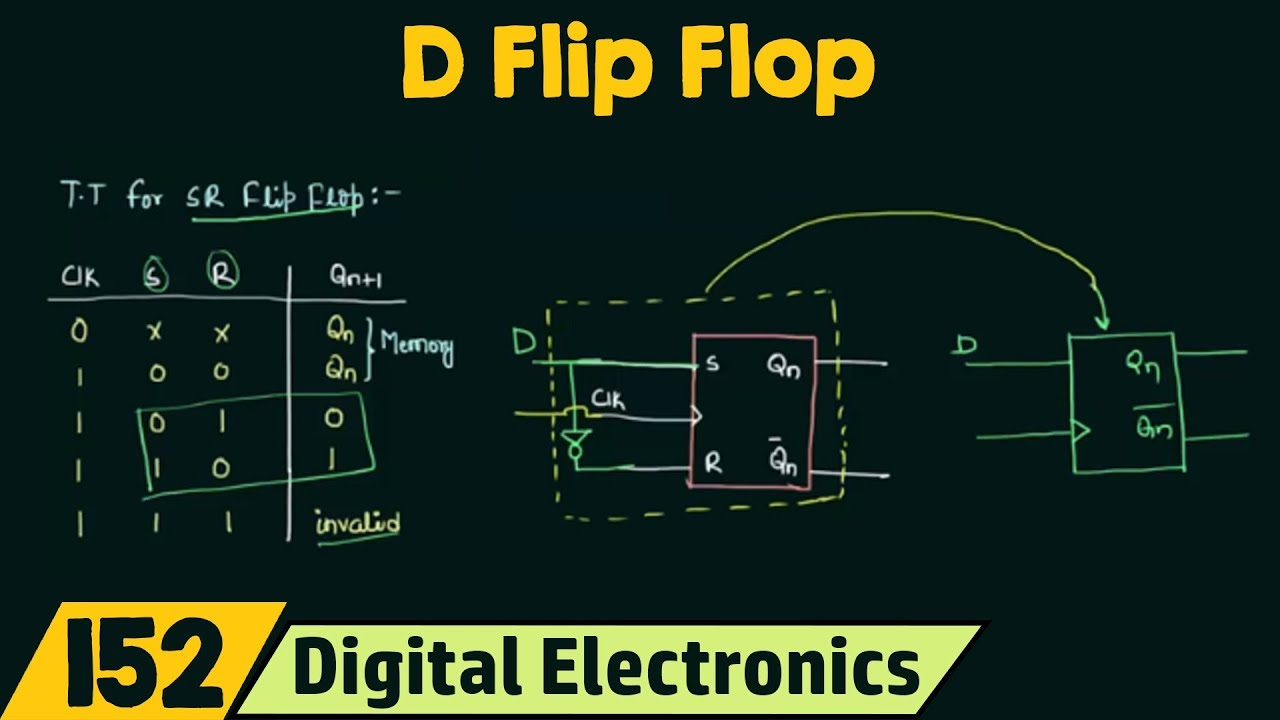
SR Flip-Flop
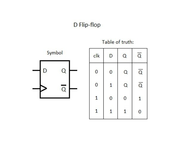
D Flip-Flop
Notice that when you set S and R, R is always the complement of S. D stands for “Data” flip-flop.
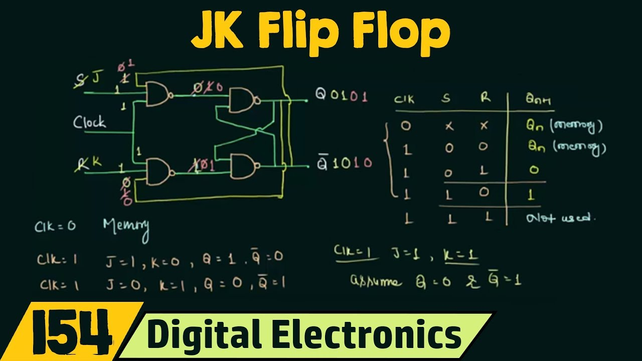
JK Flip-Flop
Generalization of D and T Flip-Flop (seen below).
As we know, S = 1 and R =1, is not used in the SR flip flop. But we implement it with JK, where when J=1 and K=1, we have a toggling action.
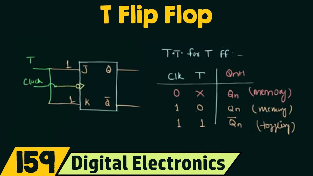
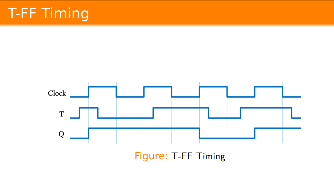
T Flip-Flop
Toggle Flip-flop, make J and K the same.
Flip-Flop Conversions
Steps:
- Identify available and required FF
- Make Characteristic Table for required FF
- Make Excitation Table for available FF
- Write boolean expression for available FF
- Draw circuit.