Radio Access Network (RAN)
BTS (2G) nodeB (3G/UMTS) eNodeB (4G/EPS) gnodeB (5GS)
The RAN manages the radio spectrum, making sure it is used efficiently and meets the quality-of-service requirements of every user. It corresponds to a distributed collection of base stations.
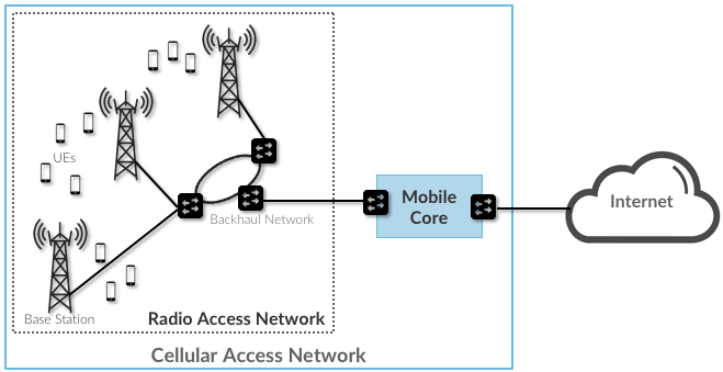
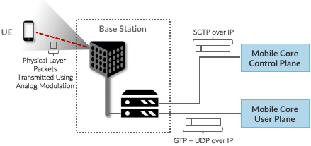
RAN High-level Architecture
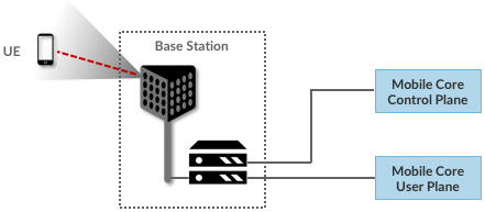
Step 1: Each base station establishes the wireless channel for a subscriber’s UE upon power-up or upon handover when the UE is active
- Wireless channel is released when the UE remains idle for a predetermined period of time.
- The wireless channel is said to provide a Bearer Service
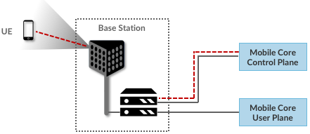
Step 2: Each base station establishes “3GPP Control Plane” connectivity between the UE and the corresponding Mobile Core Control Plane component, and forwards signaling traffic between the two.
- This signaling traffic enables UE authentication, registration, and mobility tracking
Step 3: For each active UE, the base station establishes one or more tunnels between the corresponding Mobile Core User Plane component.
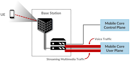
Step 4: The base station forwards both control and user plane packets between the Mobile Core and the UE.
Note
As an aside, it is noteworthy that connectivity between the RAN and the Mobile Core is IP-based. This was introduced as one of the main changes between 3G and 4G. Prior to 4G, the internals of the cellular network were circuit-based, which is not surprising given its origins as a voice network.
Step 5: Each base station coordinates UE handovers with neighboring base stations, using direct station-to-station links.
- Exactly like the station-to-core connectivity in step 4, these station-to-station links are used to transfer both control plane (SCTP over IP) and user plane (GTP over UDP/IP) packets
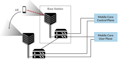
Step 6: The base stations coordinate wireless multi-point transmission to a UE from multiple base stations, which may or may not be part of a UE handover from one base station to another.
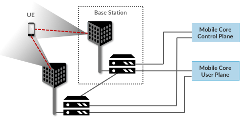
The RAN as a whole (i.e., not just a single base station) not only supports handovers (an obvious requirement for mobility), but also Link Aggregation and Load Balancing
- RAN-wide (global) decisions can be made using SDN techniques
Ran Internals
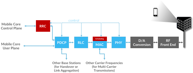
- RRC → Responsible for configuring the coarse-grain and policy-related aspects of the pipeline. The RRC runs in the RAN’s control plane; it does not process packets on the user plane.
- PDCP (Packet Data Convergence Protocol) → Responsible for compressing and decompressing IP headers, ciphering and integrity protection, and making an “early” forwarding decision (i.e., whether to send the packet down the pipeline to the UE or forward it to another base station).
- RLC (Radio Link Control) → Responsible for segmentation and reassembly, including reliably transmitting/receiving segments by implementing a form of ARQ (automatic repeat request).
- MAC (Media Access Control) → Responsible for buffering, multiplexing and demultiplexing segments, including all real-time scheduling decisions about what segments are transmitted when. Also able to make a “late” forwarding decision (i.e., to alternative carrier frequencies, including Wi-Fi).
- PHY (Physical Layer) → Responsible for coding and modulation, including FEC.