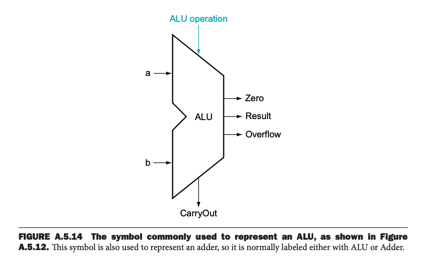
Arithmetic Logic Unit (ALU)
An ALU is a Combinational Circuit that performs arithmetic and bitwise operations on integer binary numbers.
I learned this briefly in ECE124, but I really don’t remember. See Appendix A.5 from the ECE222 textbook to review how to construct one from scratch.

RISC-V ALU
The ALU is used for the RISC-V Implementation to run the instructions, such as adding/subtracting registers, and changing branches.
To use the ALU, in addition to feeding the data itself, you need to specify the ALU control input, which is a 4-bit signal. The RISC-V ALU can take on the following functions depending on the value of its control lines:
To generate this 4-bit ALU control input, we use a small ALU control unit that has 2 kinds of inputs:
- a 2-bit control field which we call ALUOp (this is fed by the main Control Unit)
- the funct7 and funct3 fields of the instruction
- These are only used in R-Type instructions
ALUOp is set to the following values
- : For load and store instructions
- Always use ADD for ALU operation (because we always need to compute a memory address by addition)
- : For
beqinstruction- Always use SUB (to test if the subtraction of the two register values is zero, in which case we branch to the offset)
- #gap-in-knowledge but to branch to the offset, we need to do an add operation??
- : For R-type instructions
- ALU function depends on funct7 and funct3 fields
Below is a table summarizing all of this:

Now that we understand the inputs of the Control Unit, you can go to the Control Unit, you can go to the Control Unit page to understand what it actually does.
Question
Why can’t we just directly specify the ALU function in the binary instruction itself?
They talk about this idea of multiple levels of decoding on page 270.
This style of using multiple levels of decoding—that is, the main control unit generates the ALUOp bits, which then are used as input to the ALU control that generates the actual signals to control the ALU unit—is a common implementation technique.
- Using multiple levels of control can reduce the size of the main control unit.
- Using several smaller control units may also potentially reduce the latency of the control unit.
- Such optimizations are important, since the latency of the control unit is often a critical factor in determining the clock cycle time