Control Unit
The control unit is a component of a CPU that directs the operation of the processor.
- A control unit sets the values of the control signals (through control lines)
- The control unit can set all but one (PcSrc) of the control signals based solely on the opcode and funct fields of the instruction
Abstract
In the RISC-V Implementation architecture, you are going to see that there are 2 Control Units:
- Main Control Unit
- ALU control Unit (see ALU page for more info)
Main Control Unit
The main control unit takes the opcode field in order to decide the values of the control signals.
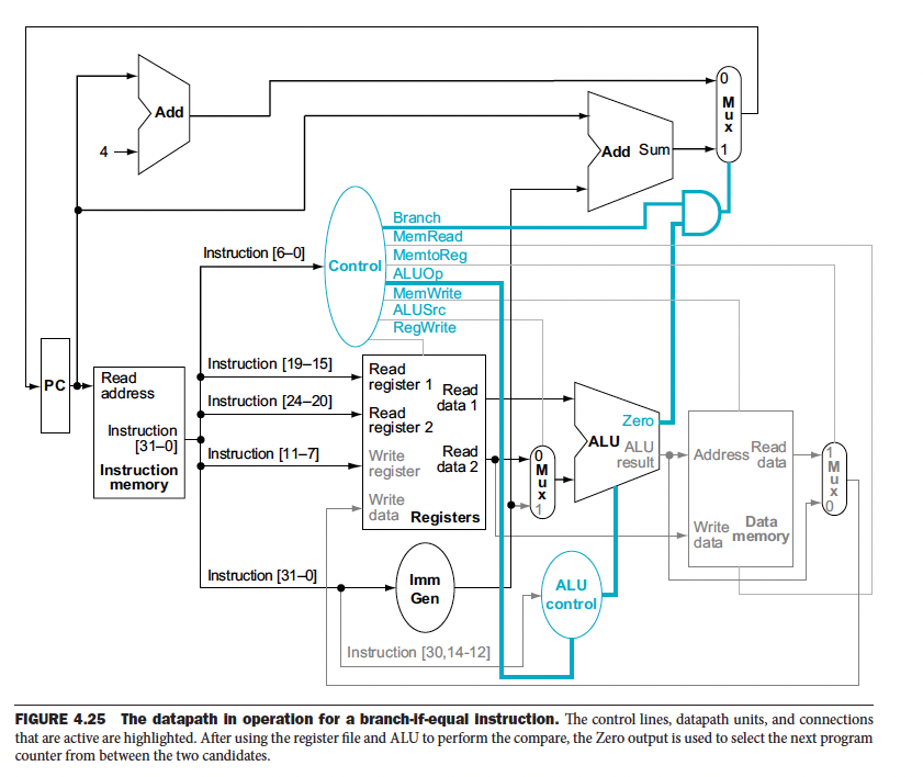
In RISC-V Implementation, we saw the abstract diagram with the control signals above certain RISC-V Implementation, we saw the abstract diagram with the control signals above certain Datapath elements.
There are 8 control signals, 2 for the ALUOp, and 6 below:
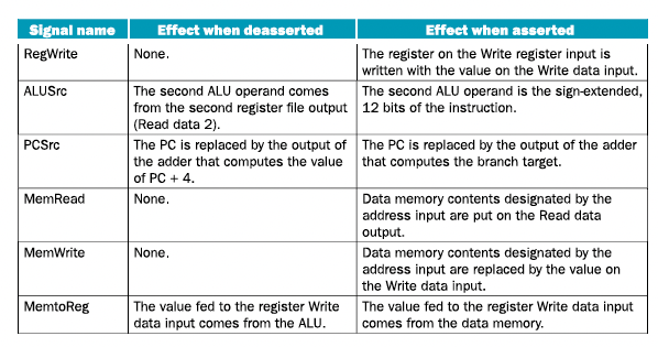
- All these control lines are set directly EXCEPT for
PCSrc, which is generated by ANDing theBranchandZerosignal out of the ALU (see below). - We will draw
ALUOpusing only a single line, but know in practice that its actually 2 bits.
So in summary, we see 7 lines coming out of the Control Unit on the diagram:
- Branch (M)
- MemRead (M)
- MemToReg (WB)
- ALUOp (2 bits) (EX)
- MemWrite (M)
- ALUSrc (EX)
- RegWrite (WB)
where
- Execution Signals (EX)
- Memory Access Signals (M)
- Write-Back Signals (WB)
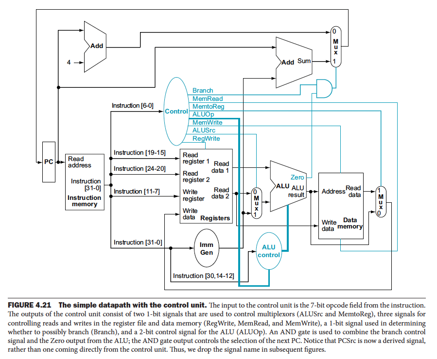
Let’s see how these control signals are actually implemented in the diagram to produce the correct results.
Branchis a 1-bit signal used in determining whether to possibly branch- Notice that PCSrc is not on the diagram because it is a derived signal, rather than one coming directly from the Control Unit, it’s the AND of Branch and Zero as we said before
Depending on what kind of instruction we are dealing with, the control line values are going to be set differently.
R-Type instructions
- The general format is `R[rd] <= R[rs1] operation R[rs2]
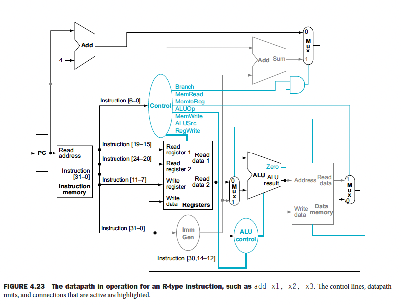
Load instruction
 Reminder: you are doing the following:
-
lw:R[rd]<= M[ R[rs1] + imm] -
sw:M[ R[rs1] + imm ] <= R[rs2] -
So for
lw, you don’t use Reg2 -
However, for
sw, you need to use x2, which holds the data that you want to put into memory
beq instruction
- The general format is
if R[rs1] == R[rs2] then PC = PC + {imm,1b’0}
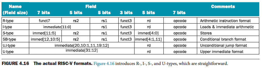 A reminder about the format of a RISC-V instruction.
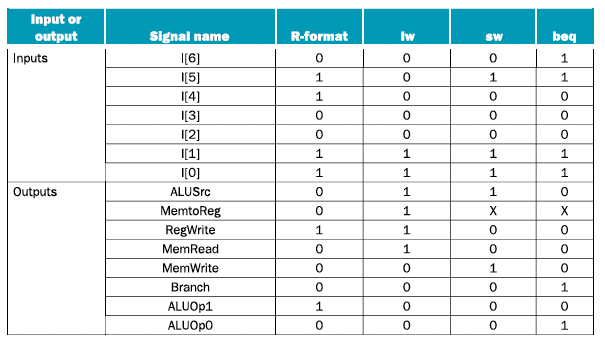
The setting of the control lines is completely determined by the opcode fields of the instruction. Below is a table showing exactly how the opcode field translates into values for control signals.
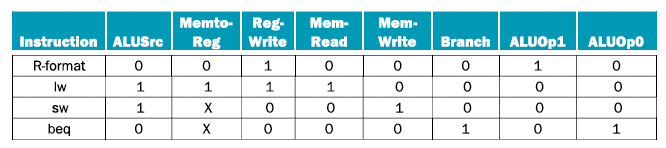
- You might notice that the opcode is 7 bits, but there are 8 control signals
- Indeed, the bits of the opcode do NOT directly map into control signals
- The Control Unit uses the truth table and implements it using a Combinational Circuit (see Appendix C) so that it can take the RISC-V instructions to set the control lines
Next, we look at improving performance by implementing Pipelining.