Camera Intrinsics
These are calculated as part of the Camera Calibration process. Parameters through the Calibration Matrix.
At NVIDIA, I saw that these can be obtained from the camera manufacturer through an EEPROM.
Distinction with Cyrill Stachniss
In my Cyrill Stachniss Camera Calibration notes, I have an extra coordinate system, the sensor plane. In there, the image plane represents the idealized projection, whereas the sensor plane represents the actual measurements (corrects for Principal Point).
Below, these directly go to the sensor plane.
Copy Pasted from Pinhole Camera Geometry
Below, I derive how we go from world image coordinate for camera intrinsics. In my Camera Calibration, we go from world image sensor coordinate system.
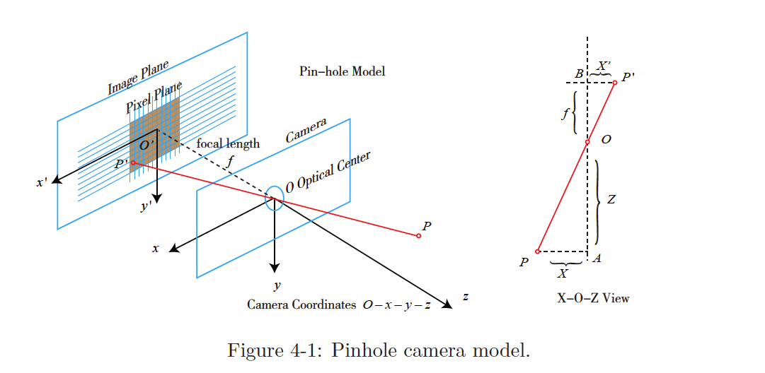
- This is the Optical Frame, the drawing on the right is a bird-eye view
Let be the camera coordinate system.
The 3D point , after being projected through the hole , falls on the physical imaging plane and produces the image point .
We define the following:
- the 3D point
- the image point
- is the physical distance from the imaging plane to camera plane is (focal length)
Then, according to the similarity of the triangles,
The negative sign indicates that the image is inverted. We can equivalently place the imaging plane symmetrically in front of the camera.
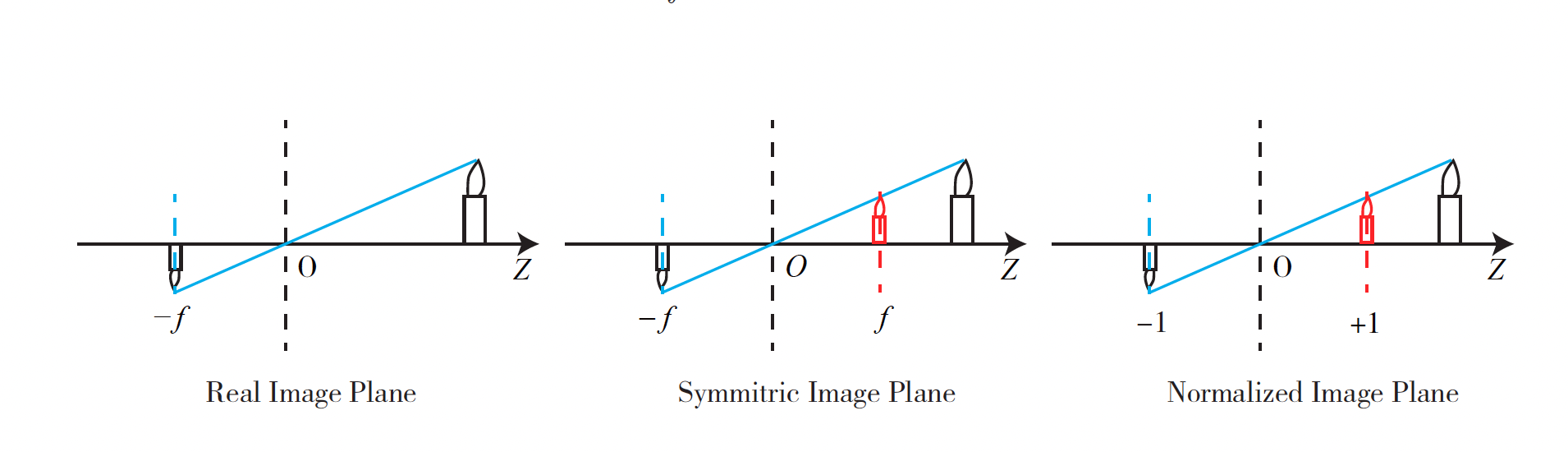
This removes the negative sign in the formula to make it more compact: So we get
So where does
f_xandf_ycome from?and are the same if you have a square pixel (no stretching). However the pixel’s width and height are different and the pixel is like a rectangle shape.
That’s why Cyrill Stachniss represented it as f times a shear factor.
Pixel Coordinates
To describe how the sensor converts the perceived light into image pixels, we set a pixel plane fixed on the physical imaging plane
Between the pixel coordinate system and the imaging plane, there is an apparent zoom and a translation of the origin:
- pixel coordinates scales times on the axis and times on
- origin is translated by
Then, the relationship between the coordinates of and the pixel coordinate is:
We then replace and with the values found previously:
- is the focal length in meters
- and is in pixels/meter, so and are in pixels.
We can write this as a matrix. Let’s put to the left side as in most books:
- Notice that LHS is a Homogeneous 2D coordinate, while RHS is non-homogeneous (Cartesian coordinates)
- denotes the camera’s inner parameter matrix, so there are 4 parameters: