Camera Calibration
Cameras have distortions. You know this after seeing Stuff Made Here’s video.
See Pinhole Camera Geometry which goes into this in more detail.
https://docs.opencv.org/3.4.3/dc/dbb/tutorial_py_calibration.html → Does intrinsics calibration
Resources
- Camera Parameters - Extrinsics and Intrinsics (Cyrill Stachniss)
- slides here
- Camera Intrinsics and Extrinsics - 5 Minutes with Cyrill
- Mapping the 3D World to an Image - 5 Minutes with Cyrill
Two parts to camera calibration:
- Camera Intrinsics: Focal length + some translation
- Camera Extrinsics: Static transforms from global frame of reference
This is something you personally saw during your time at NVIDIA.
All the matrices used:
- Intrinsic Matrix
- Extrinsic Matrix
- Projection Matrix
- Reprojection Matrix
- Essential Matrix
- Fundamental Matrix
Repositories
WATonomous
Apparently, I need to do this before doing Euclidean Clustering.
Personally, I have never done this before. It seems that F1TENTH does this, see Lab8.
Intrinsics vs. Extrinsics
Really really learned these things through NVIDIA.
Intrinsics are the parameters inside the camera (think Focal Length), whereas extrinsics are the outside parameters relative to the environment (think Static Transforms).
We need to calibrate both.
Camera Calibration notes from Cyrill Stachniss
Notation
I don’t like the notation in these videos. But I think I need to stick to it to be consistent as I learn from the material. Also, helps me to learn about coordinate systems in different contexts.
This is Camera Calibration fundamentals. Camera Parameters https://www.youtube.com/watch?v=uHApDqH-8UE&list=PLgnQpQtFTOGRYjqjdZxTEQPZuFHQa7O7Y
Slides: http://www.ipb.uni-bonn.de/html/teaching/photo12-2021/2021-pho1-20-camera-params.pptx.pdf Most fundamental equation
- Lowercase = points in image (2D)
- Uppercase = points in 3D World coordinate (3D)
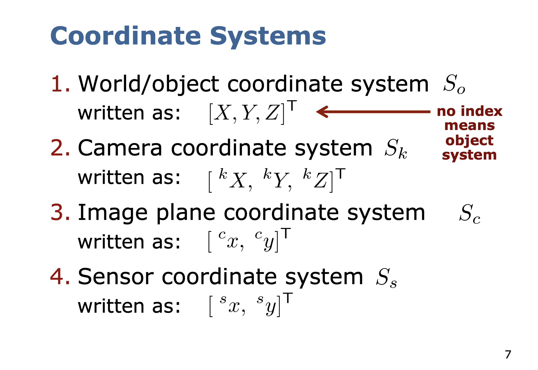
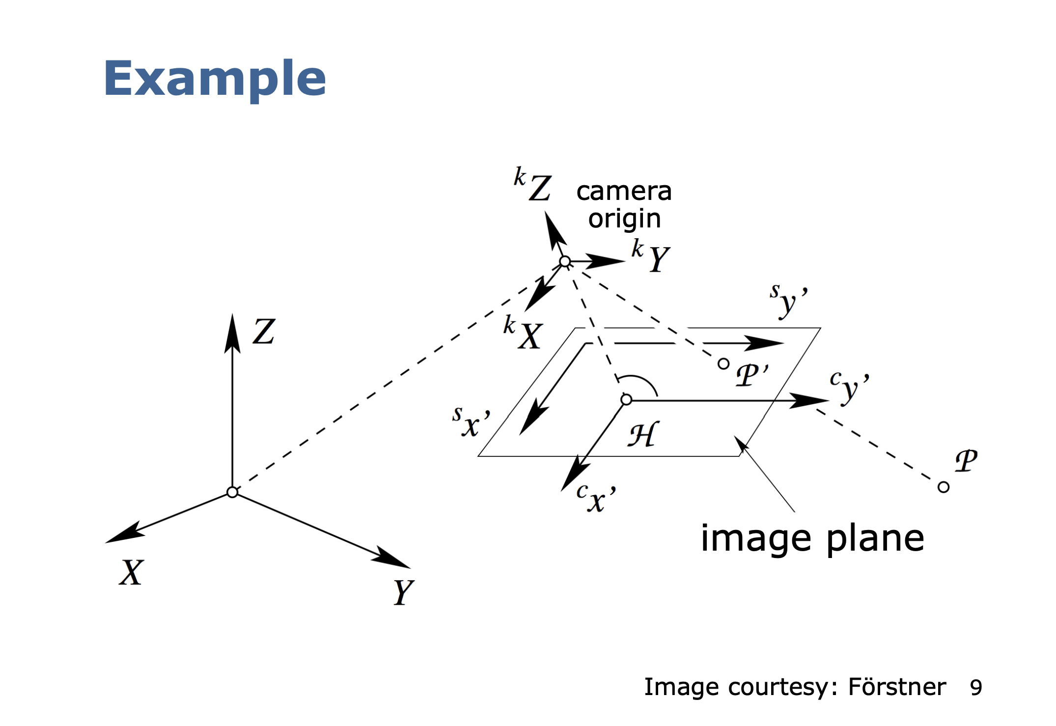
Coordinate Systems
- World/object coordinate system
- Camera coordinate system
- Image plane coordinate system
- Sensor coordinate system
Why isn't the image plane and the sensor coordinate system the same thing?
It is just a matter of a simple Affine Transformation, because you don’t know how the sensor is configured. Actually, if you look at Camera Intrinsics (written from SLAM book), there is no sensor coordinate system, the image plane assumes to be corrected to be zeroed to the Principal Point.
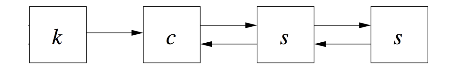
We want to compute the mapping
- is the image plane to sensor mapping
- is the camera to image mapping
- is the object to camera mapping
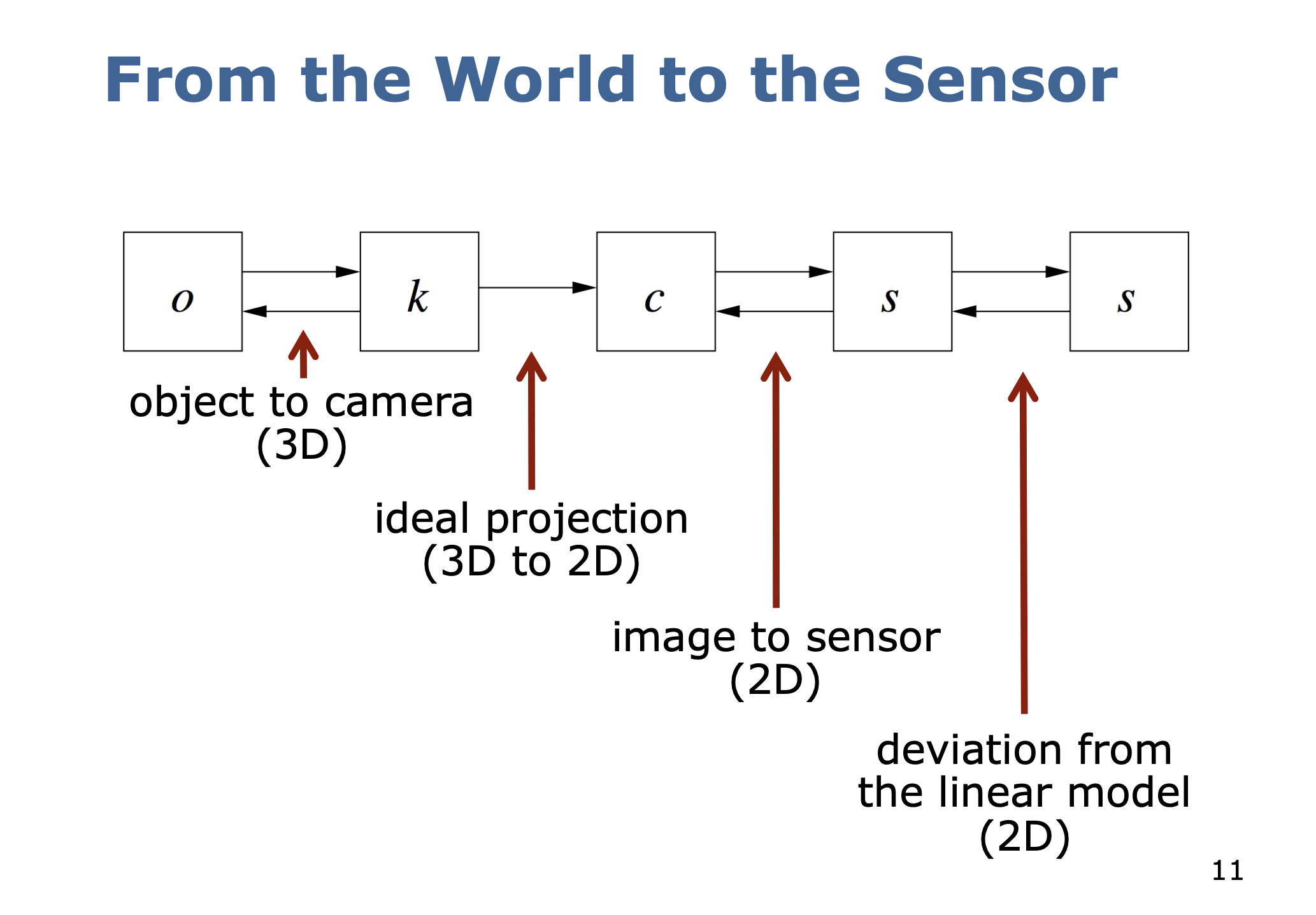
To get all these transforms, we break it down between extrinsic parameters and intrinsic parameters.
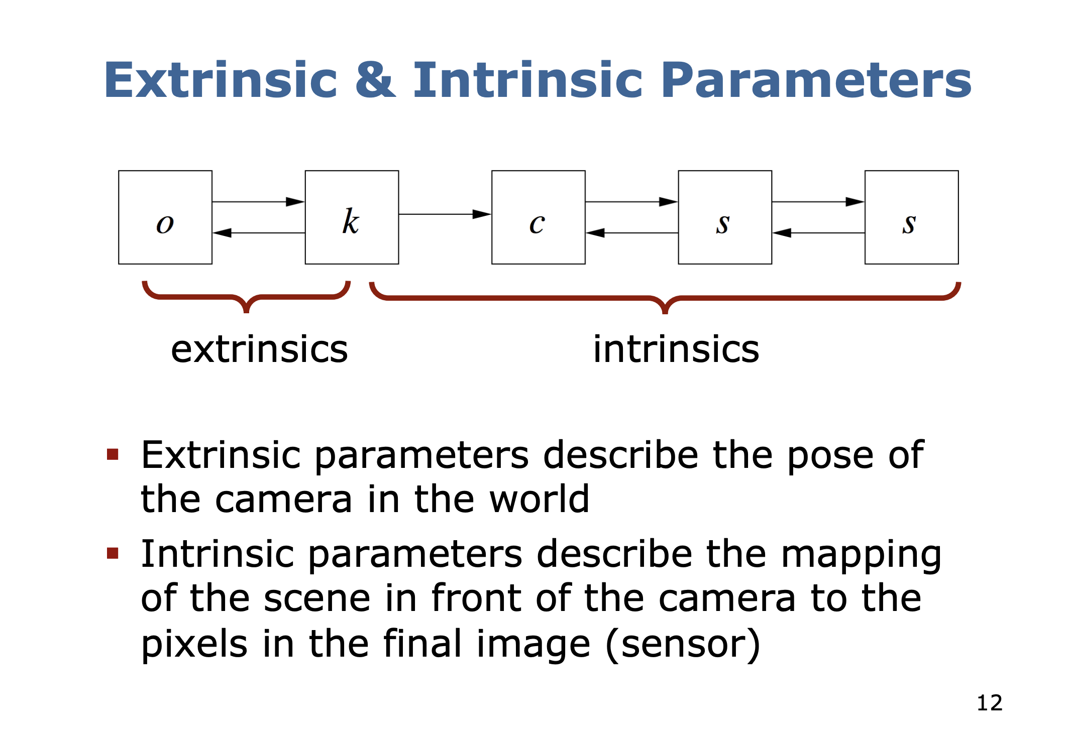
Extrinsic vs. Intrinsic Parameters
- Extrinsic parameters describe the pose of the camera in the world
- Intrinsic parameters describe the mapping of the scene in front of the camera to the pixels in the final image (sensor)
Extrinsic Parameters
- Describe the Pose of the camera with respect to the world coordinate frame
- Is an invertible transformation
- Number of parameters: 3 for position + 3 for the heading
- (although I would argue 4?? for the quaternion)
Point with coordinates in world coordinates
Center of the projection (origin of the camera coordinate system)
- sometimes also called or
- Translation between the origin of the world coordinate system and the camera coordinate system
- Rotation from to .
In Euclidean coordinates, combining translation and rotation yields
- meanings point measured in frame
I am confusion
Normally, we rotate first, and then translate, but why is it the case here that we translate first? It’s important to understand in what frames these points are expressed in. The issue is that (the translation) is expressed in the world frame, whereas usually, that translation is in terms of the target (camera) frame. Therefore, it is equivalent to .
But we like to work with Homogeneous Coordinates. We get
Italicized in in Euclidean. Not italicized is in homogeneous coordinates.
The central projection is not invertible. Why?
- because we go from 3d to 2d. There is a projection. We lose a degree of freedom.
Camera Intrinsics Steps
The camera intrinsics mapping is split into 3 steps:
- Ideal perspective projection to the image plane central projection
- Mapping to the sensor coordinate system (“where the pixels are”) an affine transformation
- Compensation for the fact that the two previous mappings are idealized
Assumption is that all rays pass through the same point (pinhole).
- This is not true in reality, because the pinhole cannot be infinitesimally small
First Mapping
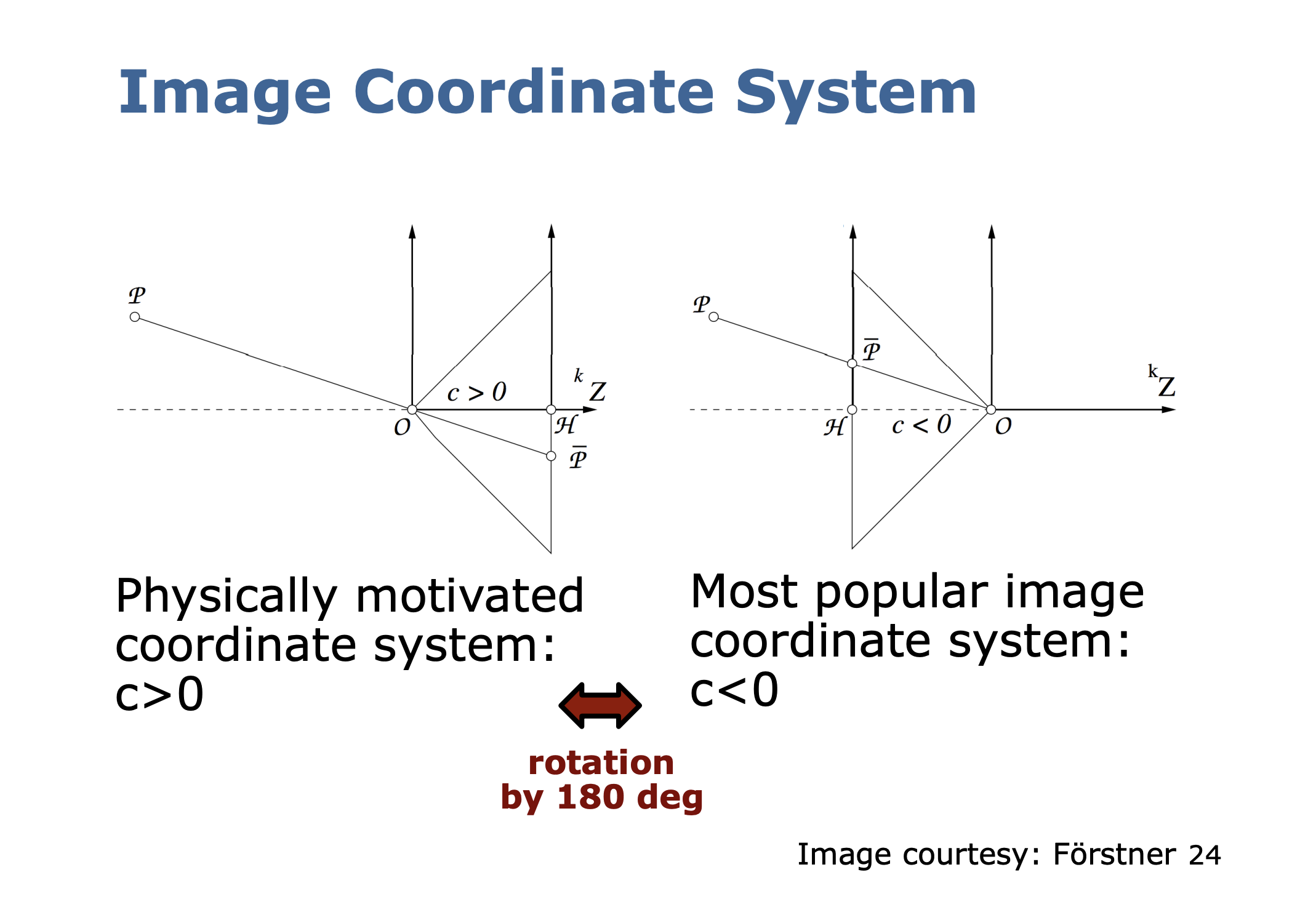
- This slide is illustrating how physically, the image plane is flipped update down and on the right
- However, we flip the image by 180 degrees to make it more convenient to work with
- The diagram is kind of confusing, I don’t really understand what is going on, I made my own diagram below
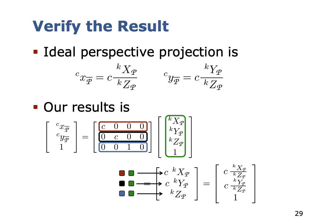
Ideal Perspective Projection
- Distortion-free lens
- All rays are straight lines and pass through the projection center. This point is the origin of the camera coordinate system
- Focal point and principal point lie on the optical axis
- The distance from the camera origin to the image plane is the constant
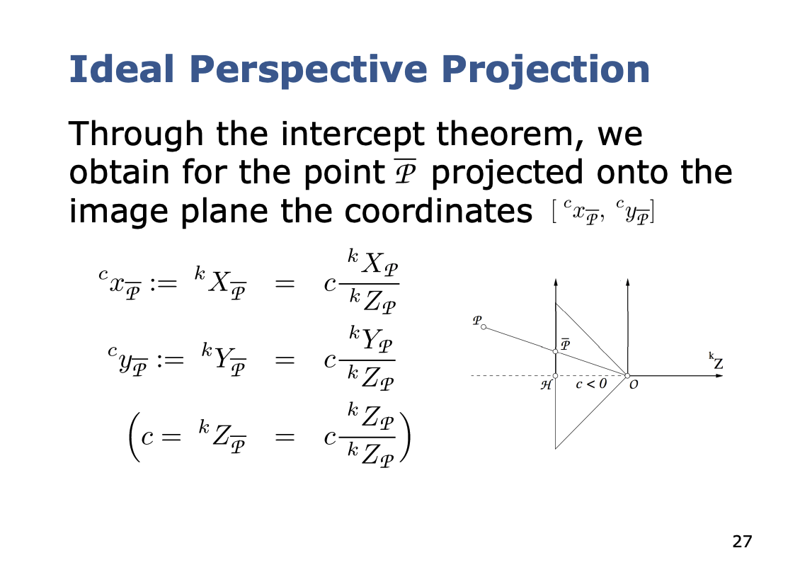
- We basically project the 3D point into the 2D world, and then drop the 3rd coordinate ()
The above are results derived from pure geometry. I spent a bit of time deriving it myself:
So basically the derivation is like similar triangles. We know that
You rearrange the terms and it’s super simple, where , so
This is simple by looking at the image that I drew below
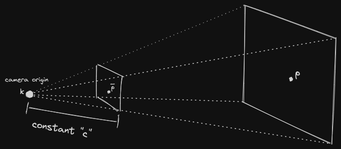
I am confused, what is
c?is the distance from the camera origin to the image plane. So then what is ?
- That that is the distance from camera origin to the actual point
- See the diagram above
How does the
Zcoordinate magically get lost?Intuitively, it makes sense, because everything is getting flattened into a 2D image plane. Because all of them have the same value, which is the constant. You’re projecting into a fixed image plane.
Now, we want to try expressing this in homogeneous coordinates, so we get the following:
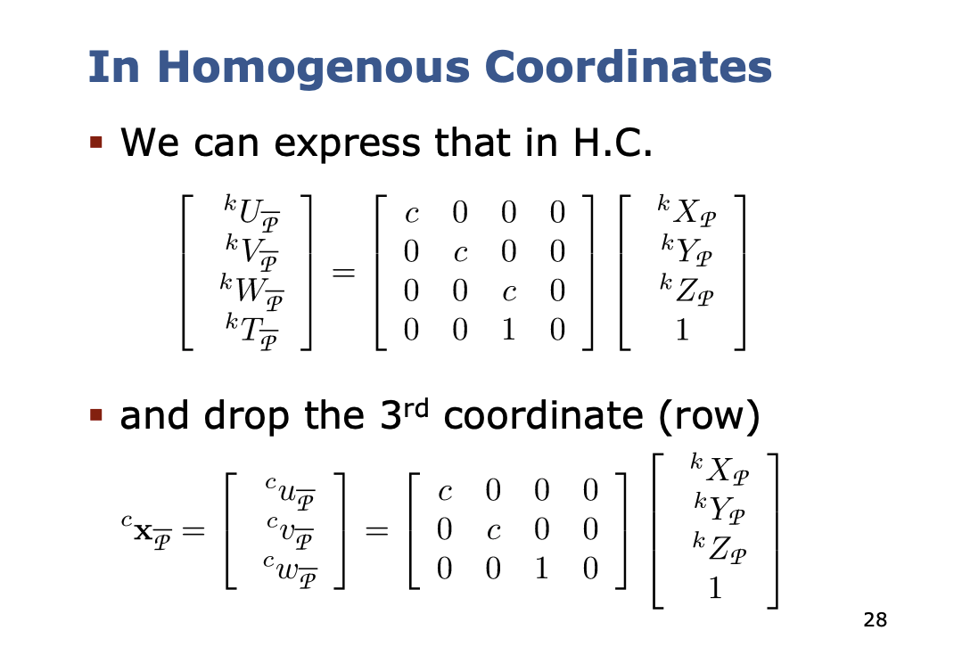
- So why do they divide it by ? Cyrill says it is to turn it from Homogenous to Euclidean Coordinates
with
Recap
So now, we can go from world to camera, and camera to image plane.
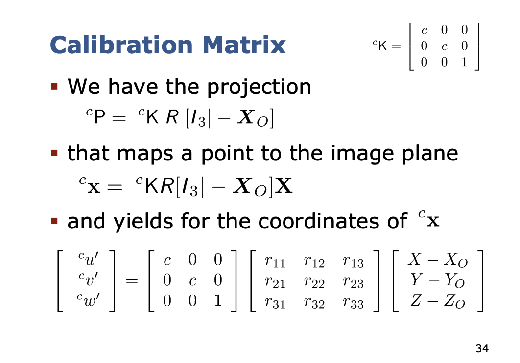
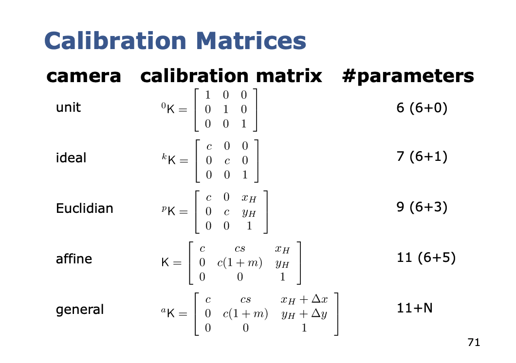
Calibration Matrix We can now define the calibration matrix for the ideal camera
- The is just a more compact way of writing a matrix, you’re essentially combining them into a single matrix, so is a matrix
- is matrix then?? Yup, remember, that isn’t the actual point
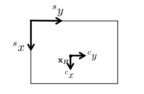
Second Mapping for Intrinsics
The next step is to move onto the sensor coordinate frame. They are different locations due to a few factors:
- Different origins (principal point)
- Scale difference
- Shear compensation
The principal point of the image is the point where the optical axis passes through the image plane.
- the point on the image plane onto which the perspective center is projected
I'm still not sure what the principal point is...
The principal point is basically the origin of our camera coordinate frame . The thing is that the sensor’s origin and the camera’s center is not exactly the same. We compensate for this shift using and , basically distance between the 2 coordinate frames and .
Why don't we just treat the camera frame as the sensor frame?
Well the whole point of working with different coordinate frames is that it is reflective of the real world. Same reason you wouldn’t have everything expressed in the same frame, see Coordinate Frame.
The origin of the sensor system is not exactly at the principal point.
- We need to compensate for this is compensated through a shift and
It represents the physical center of the sensor.
We add in the other factors:
- scale difference in and
- Sheer compensation (for digital cameras, we typically have )
so we end up with this calibration matrix
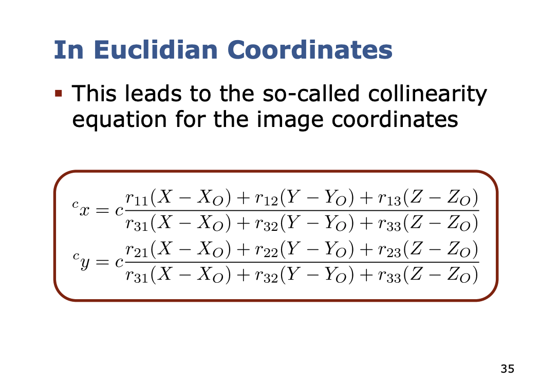
If we multiply it with the first mapping, we get
Something I realized
See the Camera Intrinsics page, but basically you end up with an unnormalized 3x1 vector, you normalize it so the third coordinate becomes 1. And that is how you lose that 1 extra dimension.
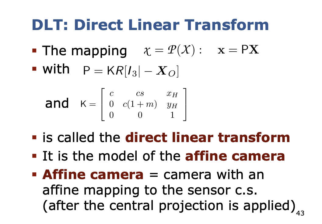
DLT: Direct Linear Transform
Has 2 meanings
- 6 extrinsics + 5 intrinsics
- 6 extrinsics: ,
- 5 intrinsics:
- Used for estimating those parameters
Affine camera = camera with an affine mapping to the censor.
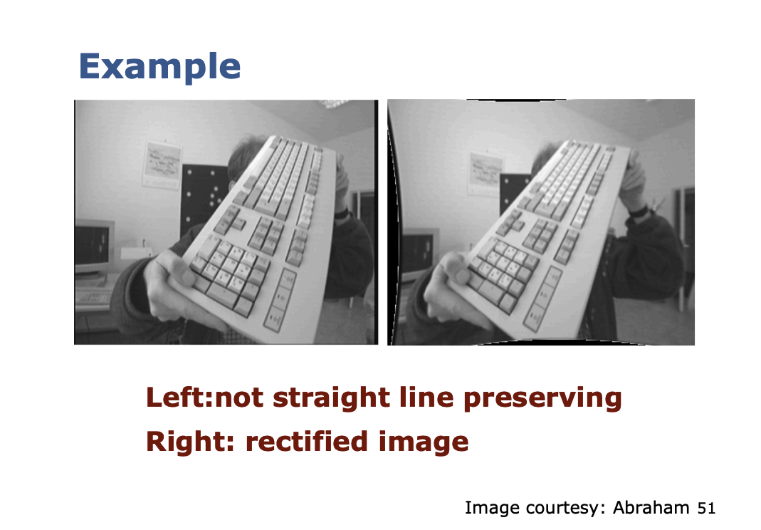
3rd mapping: Non-Linear Errors
So far, we considered only linear errors (DLT)… but the real world is non-linear.
Reasons for non-linear errors:
- Imperfect lens
- Planarity of the sensor
Idea: add a last step that covers the non-linear effects
- Location-dependent shift in the sensor coordinate system
- Individual shift for each pixel
- General mapping
Ahh, and that is what the rectified image is about. The camera calibration stuff that I learned so far has not been as relevant.
Approaches for Modeling
Large number of different approaches to model the non-linear errors
Physics approach
- Well motivated
- There are large number of reasons for non-linear errors …
Phenomenological approaches
- Just model the effects
- Easier but do not identify the problem
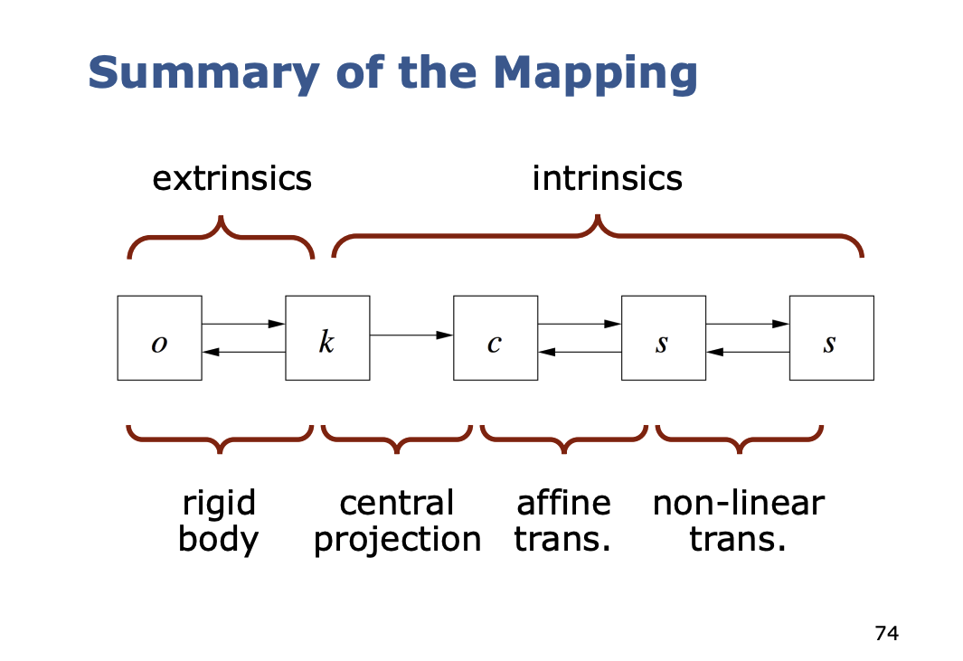
Mapping as a Two Step Process
So in general, at a higher level, we think of camera calibration in 2 steps
- Projection of the affine camera
- Consideration of non-linear effects
Getting information about the scene
Can we invert the mapping, i.e. going from pixel to world coordinates.
We can’t do that, but we can constrain where that pixel is, and then we can use a technique like SGM.
Inversion step 1:
- Iteration due to unknown in
- Start with as the initial guess
And iterate
As is often a good initial guess, the procedure converges quickly.
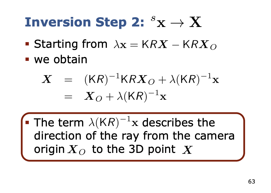
Inversion step 2:
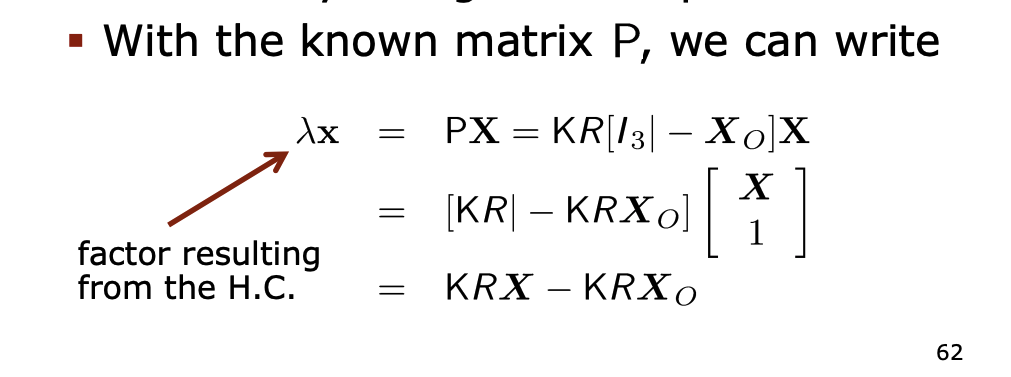
The next step is the inversion of the projective mapping
- We cannot reconstruct the 3D point but the ray though the 3D point
- With the known matrix , we can write
Classification of Cameras
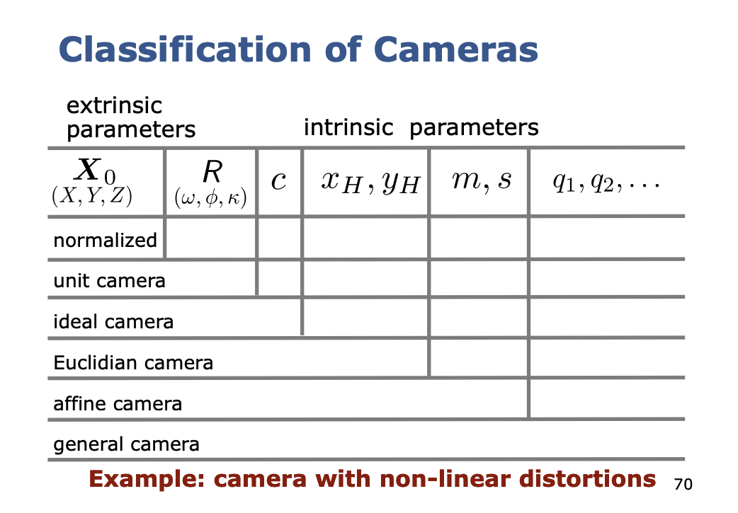
So in summary for the mapping, you should understand this part.
Distortion?
Distortion information is not accounted for in the Calibration Matrix. See CameraInfo for the pipeline.