ECE358 - Computer Networks
I will formally learn Computer Networks through this class. Though it’s in 1 year from now.
Resources
- Book: Computer Networking - A Top-down Approach, 8th Edition
- Other people’s notes
- http://gaia.cs.umass.edu/kurose_ross/online_lectures.htm
- interactive version: http://gaia.cs.umass.edu/kurose_ross/lectures.php
- goated channel https://www.youtube.com/@PowerCertAnimatedVideos/featured
- http://gaia.cs.umass.edu/kurose_ross/knowledgechecks/index.php
How is data transmitted? Several mediums
- Twisted Pair
- Coaxial Cable
- Fiber Optics
- Terrestrial Radio Channels
- Satellite Radio Channels
3 most important protocols:
- TCP
- BGP
- IP
Concepts
TODO:
- Practice the bellman ford and dijkstras
Summary slides of what is happening under the hood!!
Things to understand:
- Bits (physical layer)
- Link layer (frame)
- Network layer (packet)
- Transport layer (datagram for UDP, segment for TCP)
- Application layer (message or data)
        +-----------------------+-------------------------+
        | Application (Data)    | Telnet, FTP, etc        |
        +-----------------------+-------------------------+
        | Transport   (Segment) | TCP, UDP                |
        +-----------------------+-------------------------+
        | Network     (Packet)  | IP, ICMP                |
        +-----------------------+-------------------------+
        | Link        (Frame)   | drivers, interface card |
        +-----------------------+-------------------------+
What about datagram?
- That’s at the network layer, the teacher says ipv4 datagram
Example - ASCII (8-bit): • character: 7-bits data, 1-bit even parity • raw BER of channel = 10^{-4} • What is the probability that a character is sent in error to the layer above when no parity bit? • What is the probability that a character is sent in error to the layer above when a single-bit parity (8-bits), • parity-bit gives 3 orders of magnitude improvement in a simple case (note that we apply it to characters). However it is expensive: the overhead is 1/7=14%!
Chapter 1: Nuts and bolts of the internet
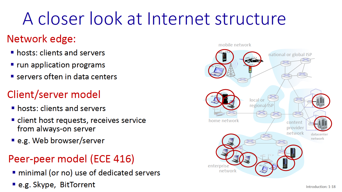
Hosts = end systems Packet switches = forward data packets
- includes routers, switches
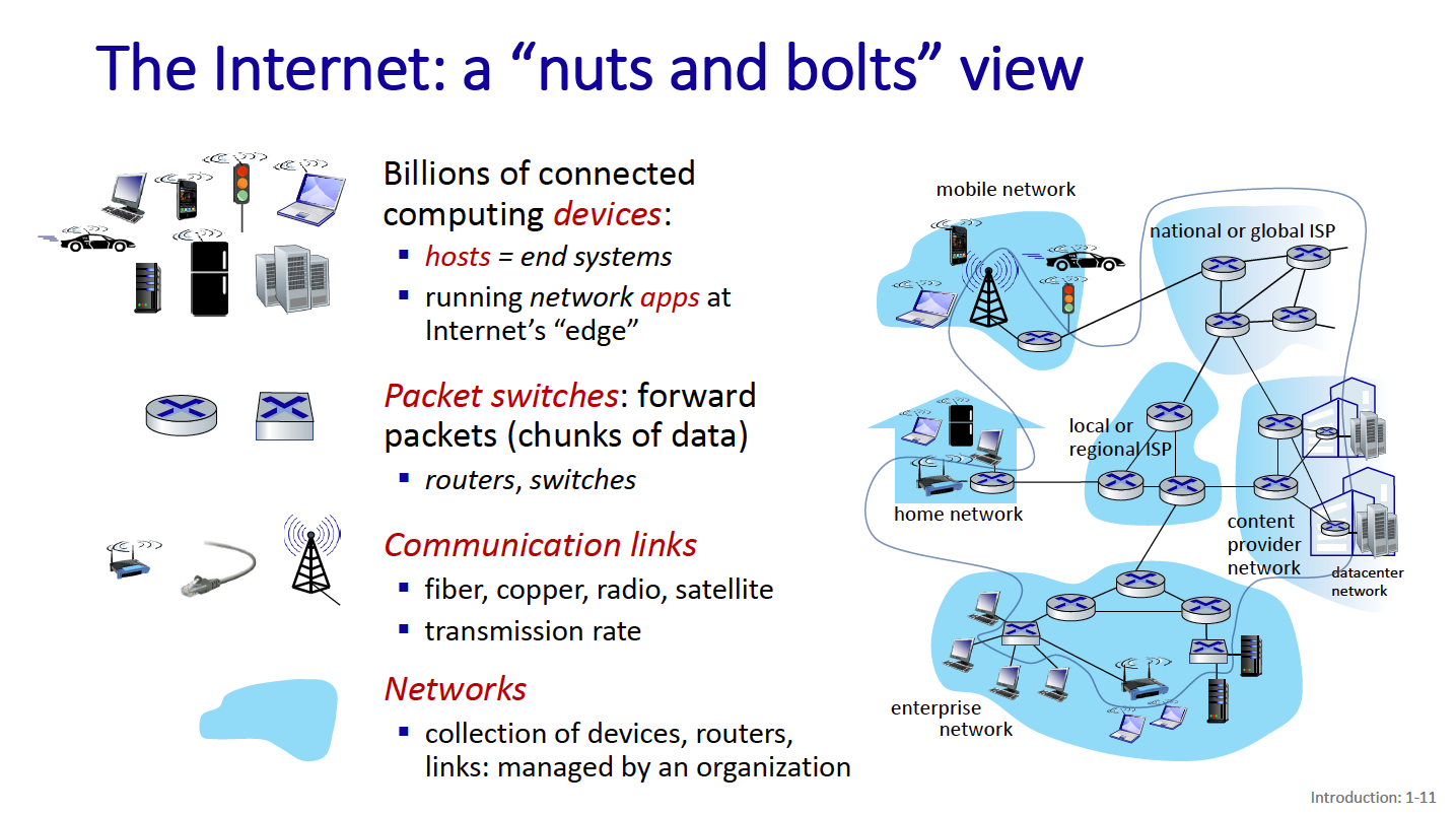
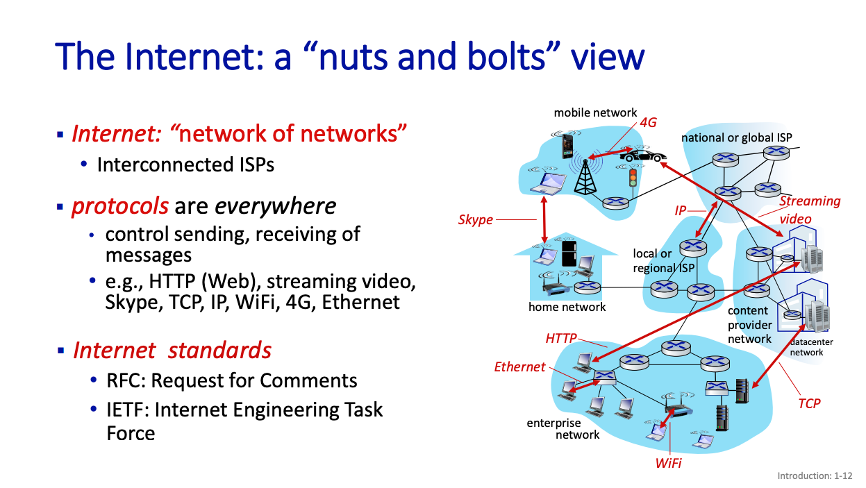
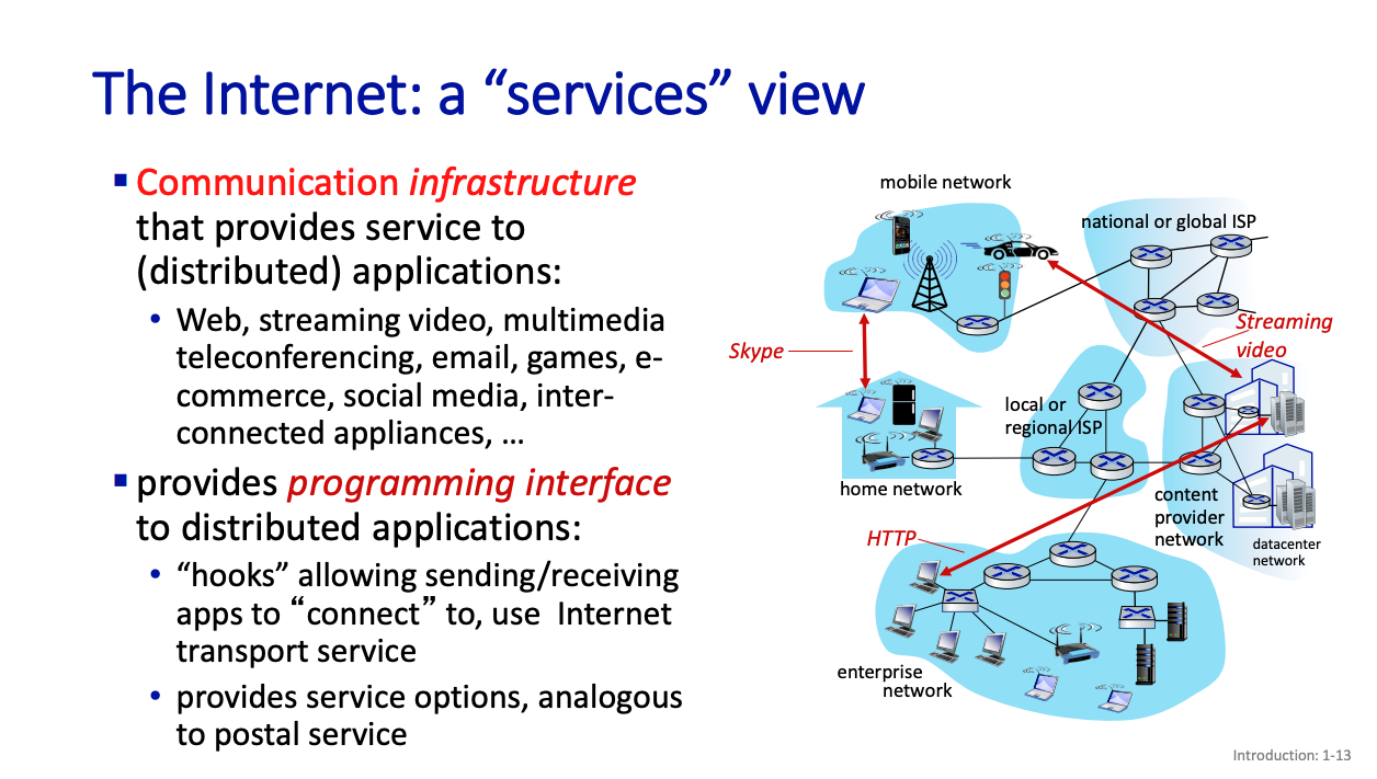
At the center of these, we have protocols.
Protocols
Protocols define the format, order of messages sent and received among network entities, and actions taken on message transmission, receipt.
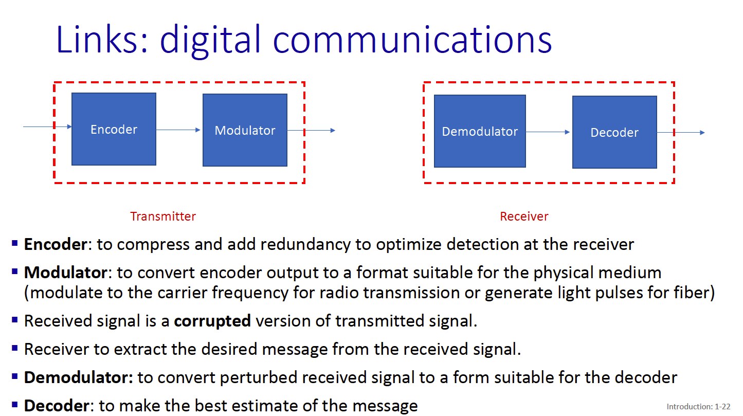
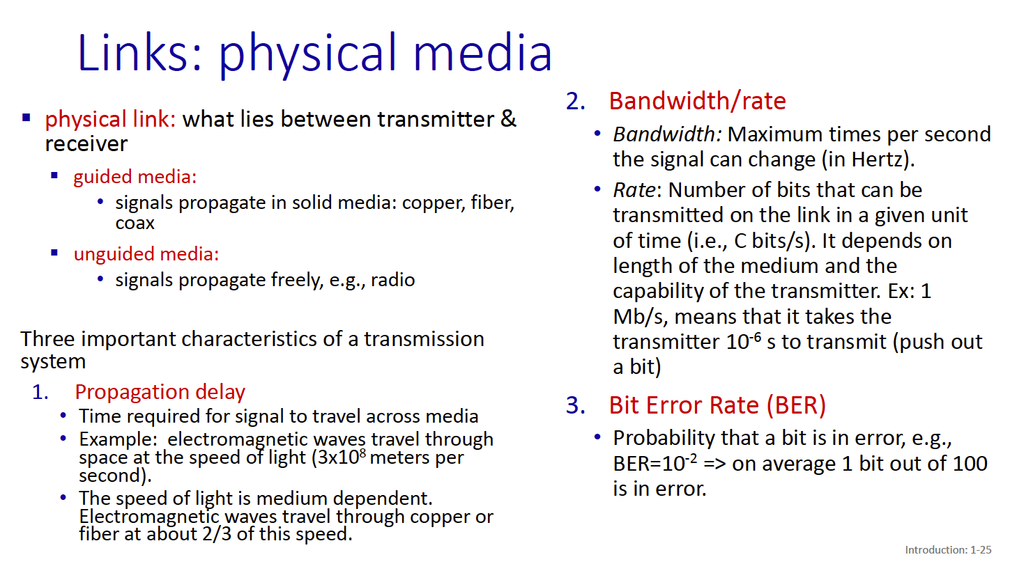
There are 3 important characteristics of a transmission system:
- Propagation delay
- Bandwidth/rate
- Bit error rate
There are a few physical media through which the link can be “implemented”:
- Twisted Pair
- two insulated copper cables. This is used for like ethernet
- Coaxial Cable
- Two concentric copper cables. Enables broadband, multiple frequency channels on cable
- Fiber Optics
- Carries light pulses. Has low error rate over long distances. High speed operation
- Wireless Radio (it is Half-Duplex)
How to connect end systems to edge router?
- There are residential access networks
- Institutional access networks (school, company)
- Mobile Access networks (4G/5G)
Residential access networks
- Digital-subscriber line
- Cable-based access
Fiber to the home.
There’s the Digital Subscriber Line.
Two competing optical technologies
- Passive Optical network (PON)
- Active Optical Network (AON): switched Ethernet
Switching
This is a pretty important topic.
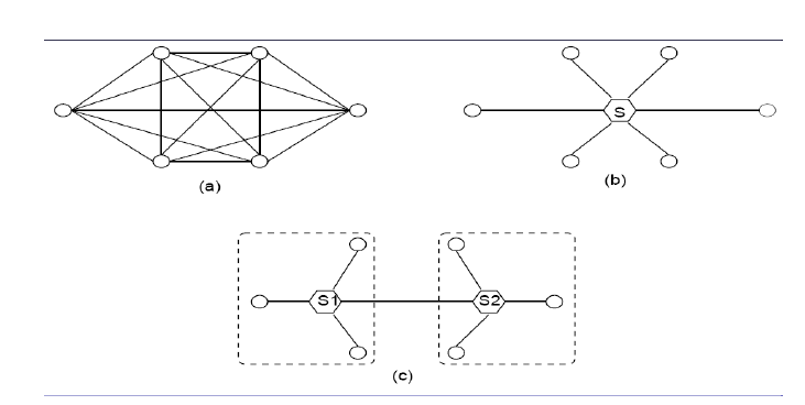
There are 3 ways to set up switching (more on this in the network layer chapter):
- Fully meshed
- Everything connected to a central switch
- Hierarchical network with inter-switch links
The Network Core
- mesh of interconnected routers
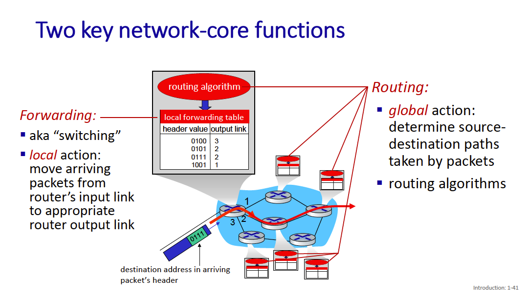
The network core has 2 main functions:
- Forwarding
- Routing
 packet-switching: hosts break application-layer messages into packets
- network forwards packets from one router to the next, across links on path from source to destination
- A packet from your computer to a server might cross many many routers (and links)
There’s packet switching and circuit switching?
- We call it packet switching because the host breaks the application-layer messages into packets
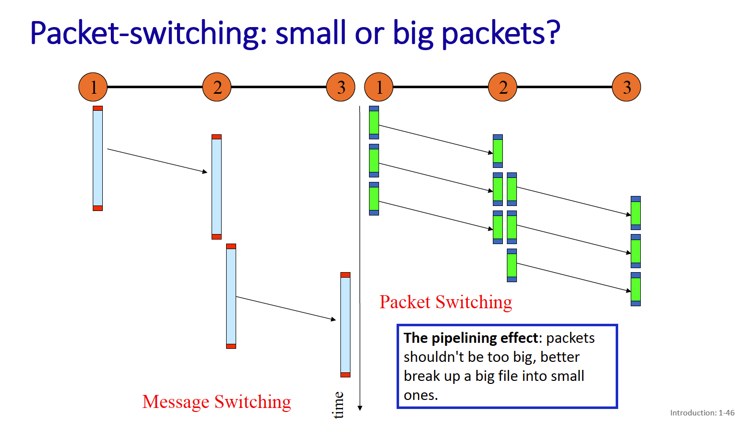
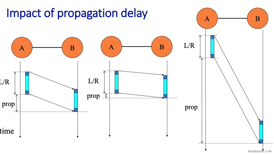
Packet transmission delay = L/R
- L (bits)
- R (bits/sec)
store and forward: entire packet must arrive at router before it can be transmitted on next link
Smaller packets are nicer because you can get pipelining behavior.
- The pipelining effect: packets shouldn’t be too big, better break up a big file into small ones.
We show Propagation Delay
The alternative is circuit switching:
- network resources are statically divided into small pieces called circuits (once and for all)
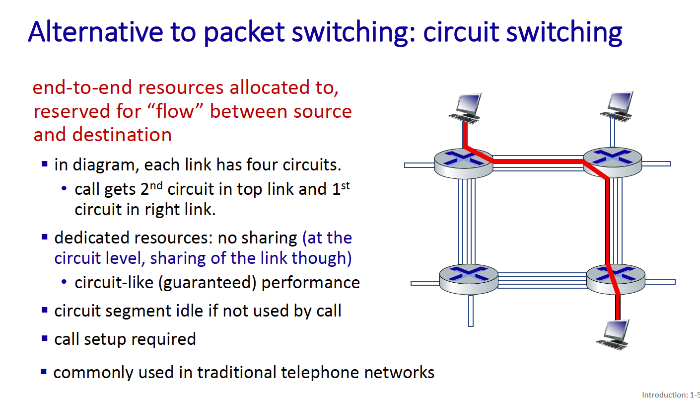
- Circuit is a logical path established through multiple physical links and switches, connecting two endpoints for the duration of a call.
Can parts of the circuit be shared? YES!
The circuit established for a phone call is not entirely composed of dedicated, exclusive physical lines. Instead, the circuit is a combination of dedicated segments (like your home line to the central office) and shared segments.
for circuit switching, you divide into 2 things:
- FDM (frequency-division multiplexing) - divide into frequency bands
- TDM (time-division multiplexing) - divide into different time slots
Circuit switching is not super efficient because users get a dedicated bandwidth.
- circuit segment idle if not used by call
In circuit switching, why can't the bandwidth be dynamically allocated?
In circuit switching, there is no mechanism to continuously monitor and reallocate bandwidth in real-time. The design is static in nature.
In packet switching, the bandwidth is dynamically allocated. Multiple users can share the same link.
In circuit switching, each user has dedicated resources, which results in a waste of capacity when users are not fully utilizing their connections. In packet switching, users share the link capacity dynamically, allowing the network to efficiently handle many more users as long as their active usage periods do not overlap significantly.
Internet Structure
Hosts connect to Internet via access Internet Service Providers (ISPs).
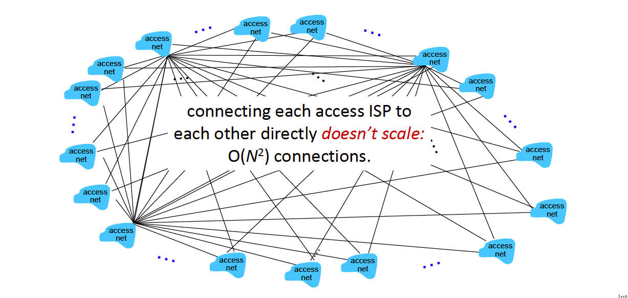
There are global ISPs, since connecting ISPs to each other is not super feasible…
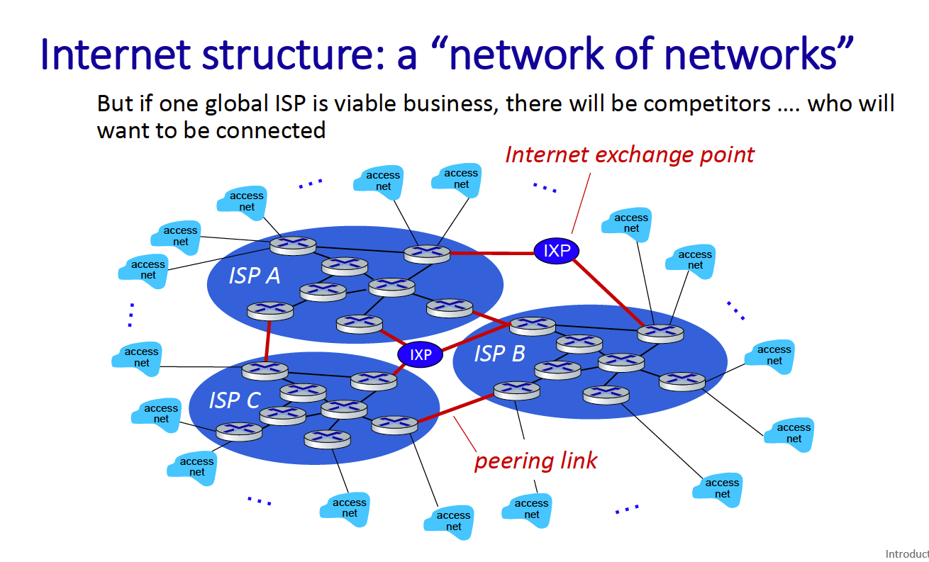
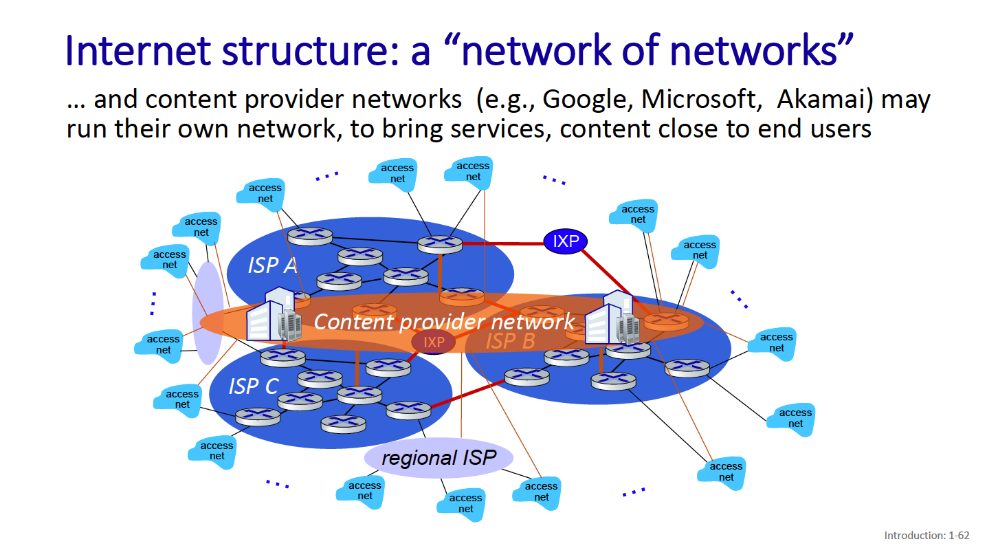
There are also content provider networks - these connect their data centers to the internet bypassing tier1
QoS defines the quality of service, how reliable do you want your network to be? Some metrics:
- packet loss
- Delay
- privacy
- security
It’s expensive to support.
Packet loss happens when the buffer holding queued packets fills up.
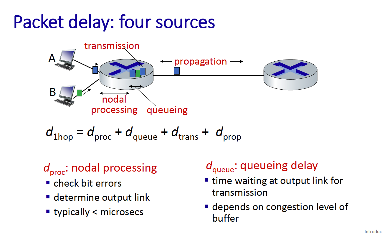
Packet delay, 4 sources:
- Transmission
- Nodal processing
- Queuing
- Propagation
Packet queuing delay is revisited: queuing delay = L * a / R
- L is packet length
- a is average packet arrival rate
- R is the link bandwidth (bit transmission rate)
If La/R ~ 0 → queuing delay is small If La/R = 1 → delay is large If La/R > 1 → more work is arriving than can be serviced!
Layers of Internet
See layers of ip. Why do you have layers?
- Explicit structure allows identification, relationship of system’s pieces
- Modularization eases maintenance
Layers of the internet protocol:
- Application Layer: support network applications
- HTTP, IMAP, SMTP, DNS
- Transport layer: process
- TCP and UDP
- Network layer
- IP, routing protocols
- Link layer: data transfer between neighbouring network elements
- Ethernet: 802.11
- physical layer
- Bits on the wire
Chapter 2: Link Layer
There are 2 types of links:
- Point-to-point
- Point-to-multipoint
A frame encapsulates a datagram.
There’s this analogy:
- transportation analogy:
- trip from Waterloo to Lausanne
- limo: Waterloo to YYZ
- plane: YYZ to Geneva
- train: Geneva to Lausanne
- tourist = datagram
- each transport leg = communication link
- transportation mode = link-layer protocol
- travel agent = routing algorithm
Services that the link layer provides
- framing, link access (compulsory)
- error detection (not even compulsory)
- error correction
Physically, how does it work?
- There’s a Network Interface Card
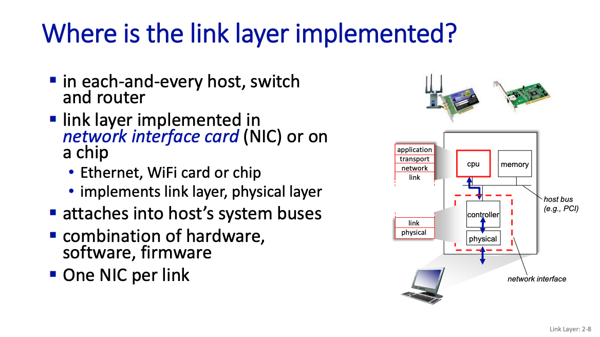
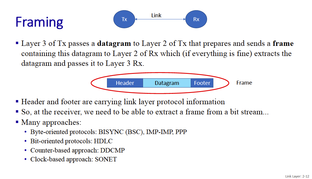
Framing is a common approach.
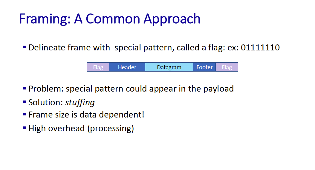
There is that one problem where your flag could appear in the payload. So you implement bit stuffing to ensure that your payload doesn’t contain the flag.
flag or idle pattern in data:
- if 5 successive 1s, insert 0 (bit stuffing)
- unstuff at receiver
Error detection is done at all layers (l2 link, l3 network, l4 transport)
Error detection is pretty complicated, the simplest is by doing parity checking.
You can also do a 2d parity check.
Then, the teacher goes through examples of how to calculate this.
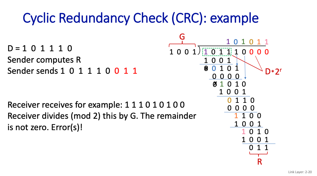
Then, there’s the Cyclic Redundancy Check, which allows you to check for errors
- more powerful error-detection coding
- D: data bits
- G: bit pattern
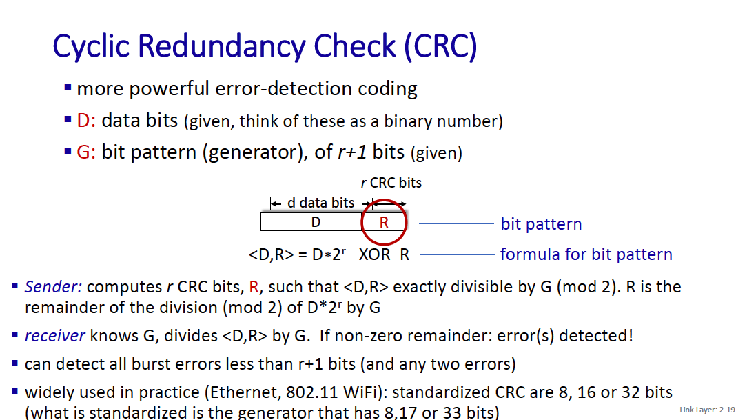
If L = 4 bits, we will append 3 bits
- Cyclic Redundancy Check (CRC) - Part 1
- Cyclic Redundancy Check (CRC) - Part 2
- Cyclic Redundancy Check (Solved Problem)
So the process is just taking XOR the whole time.
On the receiver side, if it gets 0 as the remainder, then it knows that there are no transmission errors!! So smart.
Error correction is much harder Correction technique: correct error at receiver
- computationally expensive
- high overhead
- may be useful for real-time communication or for long, fat pipes or for very noisy channels.
Packet vs. frames?
Sending the data in frames is common.
- Wait, in chapter 1, we were talking about packets. This is lower level, it’s frames?
- It’s a 1-to-1 relationship between packets and frames
Retransmission
So if you don’t correct, you can consider retransmitting.
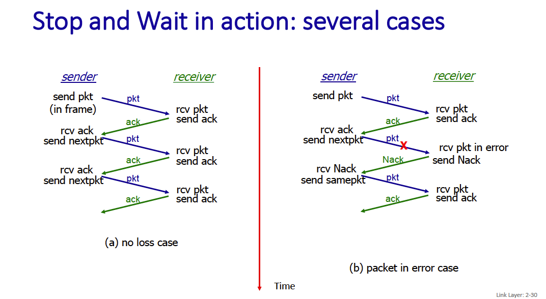
Stop and Wait
Stop and wait is the simplest mechanism: sender sends one packet (in a frame), then waits for receiver response.
We will need:
- acknowledgements (ACKs): receiver explicitly tells sender that pkt received OK
- negative acknowledgements (NAKs): receiver explicitly tells sender that pkt had errors (sender retransmits pkt on receipt of NAK)
- maybe other things to be discovered
Performance of stop-and-wait (umm im not sure if i need to know this)
- U sender: utilization – fraction of time sender busy sending
- G: goodput – # of successful data received/sec (unit of packet/sec, bit/sec etc.)
- L: length of frame carrying data
- A: length of frame carrying ACK
Pipelined retransmission mechanisms
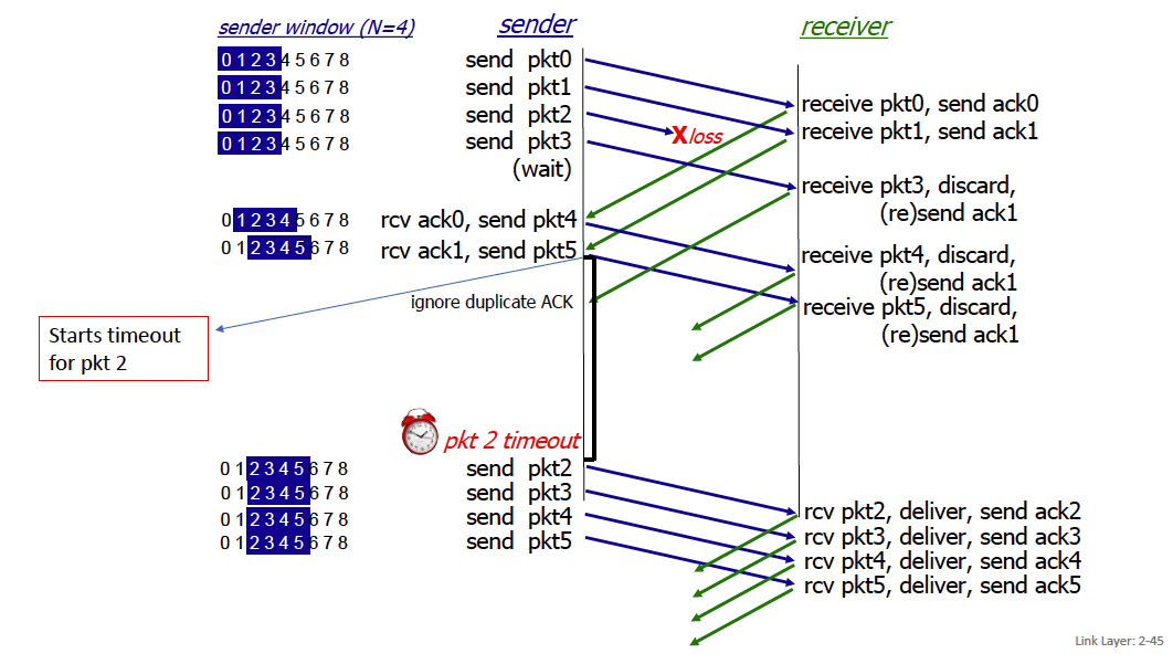
Go-back-N: big picture:
- Sender can have up to N unacked pkts in pipeline
- Rcvr only sends cumulative ACKs and does not keep pkts out of order (receive buffer size = 1)
- Doesn’t keep packet if there’s a gap
- Sender has timer for oldest unacked pkts
- If timer expires, retransmit all unacked packets
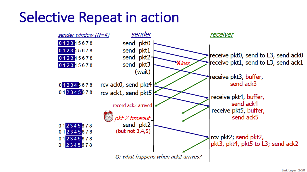
Selective Repeat: big picture
- Sender can have up to N unacked pkts in pipeline
- Rcvr keeps packets out of order, acknowledges individual frames (no more a request but a real ACK)
- Sender maintains timer for each unacked pkt • When timer expires, retransmit only unack pkt
For go-back-n
Sender
- sender: “window” of up to N, consecutive transmitted but unACKed packet
- cumulative ACK: ACK(n): ACKs all packets up to, including seq # n
- on receiving ACK(n): move window forward to begin at n+1
- timer for oldest in-flight packet
- timeout(n): retransmit packet n and all higher seq # packets in window
When there’s a timeout, the sender sends the window out again.
ACK-only: always send ACK for correctly-received packet so far, with highest in-order seq #
- may generate duplicate ACKs
- need only remember rcv_base on receipt of out-of-order packet:
- discard (doesn’t buffer) out of order pkts
- re-ACK pkt with highest in-order seq #
Selective repeat
In selective repeat, the receiver individually acknowledges all correctly received packets and manages a received window
- buffers packets, as needed, for eventual in-order delivery to upper layer
- sender times-out/retransmits individually for unACKed packets
- sender maintains timer for each unACKed pkt
- sender window
- if next available seq # in window, send packet timeout(n):
- resend packet n, restart timer ACK(n) in its window:
- mark packet n as received
- if n smallest unACKed packet, advance window base to next unACKed seq #
Receiver packet in its window
- send ACK(n)
- out-of-order: buffer
- in-order: deliver (also deliver buffered, in-order packets), advance window to next not-yet-received packet packet in [rcvbase-N,rcvbase-1]
- ACK(n) otherwise:
- ignore
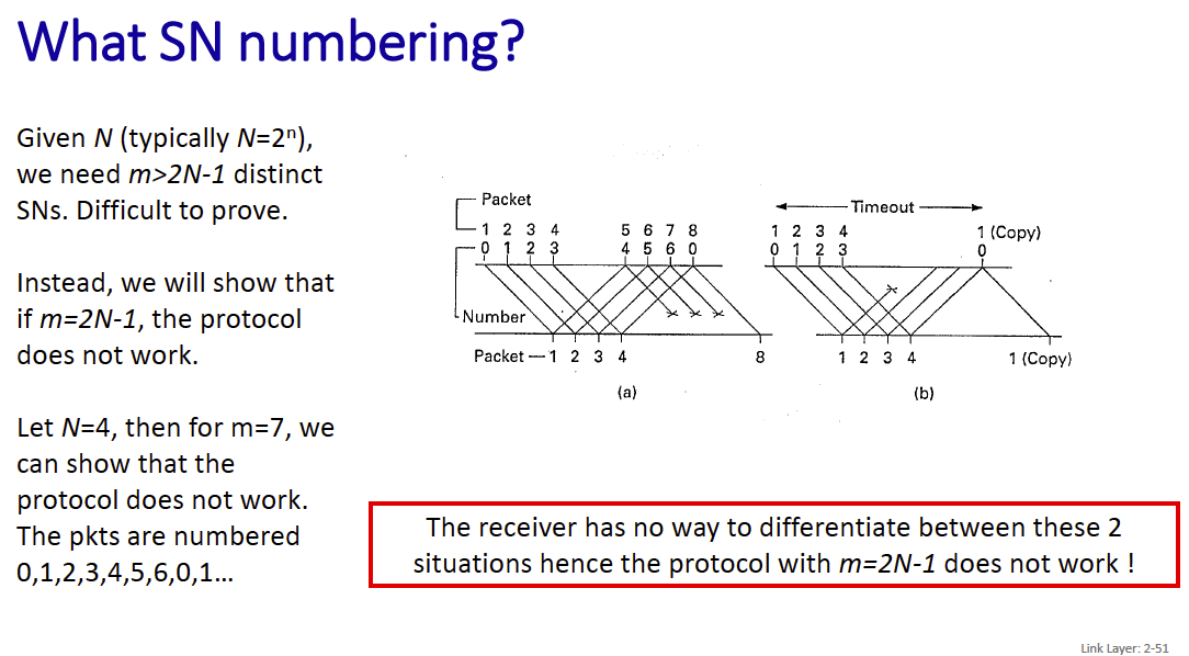
SN Numbering (Sequence numbering) Given N (typically ), we need distinct SNs. Difficult to prove. Instead, we will show that if m=2N-1, the protocol does not work.
What is N and m here?
N represents the size of the window, and m represents the range of sequence numbers that are available.
Multiple Access Protocols
Multiple Access Mechanism
distributed algorithm that determines how nodes share channel, i.e., determine when node can transmit communication about channel sharing must use channel itself!
- no out-of-band channel for coordination.
There are 2 broad classes:
- scheduling via a control node (centralized)
- random access (decentralized)
- allow collisions
- “recover” from collisions
The ancestor of scheduling was polling, where the master invites other nodes to transmit in turn.
Scheduling
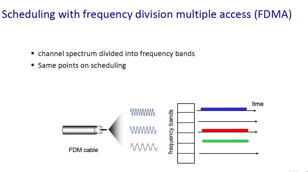
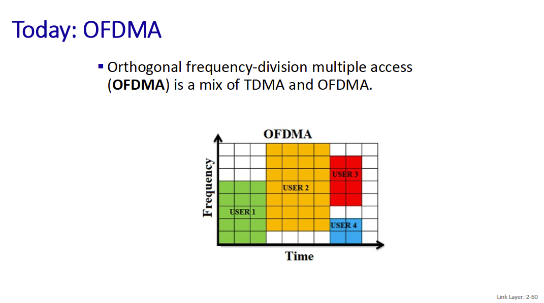
The time is divided in time slots and there is a repeating cycle (unfortunately called a frame): in the drawing the frame is made of 6 time slots.
Which time slots are allocated to a station depend on the controller. The controller can allocate time-slots in a static or dynamic way.
In the dynamic case, the allocation information is sent through maps that are broadcast regularly (e.g., every 10 ms)
Random Access
Random access protocols This is to deal with the situation where two or more nodes want to transmit at the same time.
There is no a priori coordination among nodes.
random access MAC protocol specifies:
- the degree of politeness
- how to detect collisions
- how to recover from collisions (e.g., via delayed retransmissions)
There are 2 main random access MAC protocols that are covered in class:
- ALOHA
- CSMA
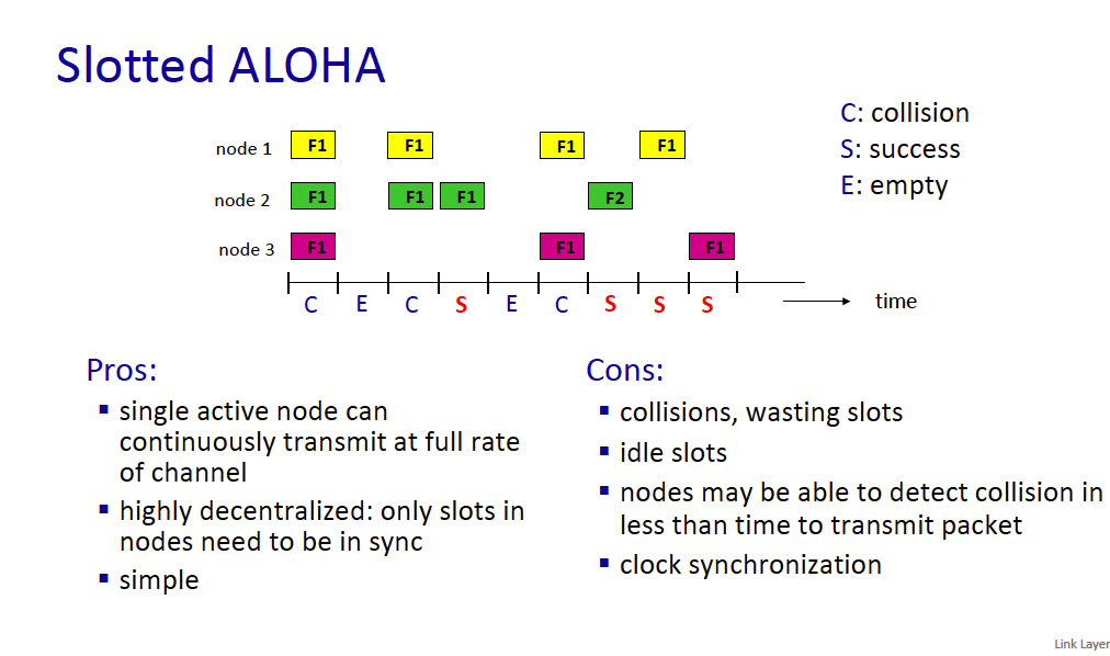
Slotted ALOHA assumptions:
- all L2 frames same size
- time divided into equal size slots (time to transmit 1 L2 frame)
- nodes start to transmit at slot beginning
- nodes are synchronized
- if 2 or more nodes transmit in slot, all nodes detect collision at the end of the slot (before the next slot) and all data is useless
operation:
- when node obtains fresh L2 frame, transmits in next slot and focuses on that frame till success
- if no collision: node is done with that frame and can send another one if any
- if collision: node retransmits frame in each subsequent slot with probability until success ( from my internet research)
efficiency: long-run fraction of successful slots (many nodes, all with many frames to send)
- suppose: N nodes with many frames to send, each transmits in slot with probability p. How to choose p?
- prob that given node has success in a slot =
- prob that any node has a success =
- max efficiency: find p* that maximizes (easy to show that p*=1/N)
- for many nodes, take limit of as N goes to infinity, gives:
- max efficiency = 1/e = .37
- at best: channel used for useful transmissions 37% of time!
unslotted Aloha: simpler, no synchronization
- when frame first arrives: transmit immediately
- collision probability increases with no synchronization:
- frame sent at t0 collides with other frames sent in [t0-L/R,t0+L/R]
- If a collision occurs (when two or more stations transmit simultaneously), the users wait for a random amount of time and then retransmit.
- pure Aloha efficiency: 18%

CSMA (carrier sense multiple access) simple CSMA: listen before transmit:
- if channel sensed idle: transmit entire frame
- if channel sensed busy: defer transmission
- human analogy: don’t interrupt others!
collisions can still occur with carrier sensing:
- propagation delay means two nodes may not hear each other’s just-started transmission
- collision: entire packet transmission time wasted
- distance & propagation delay play role in determining collision probability
That’s why you have an improvement with CSMA/CD, where CD stands for collision detection.
CSMA/CD reduces the amount of time wasted in collisions
- transmission aborted on collision detection
Old-fashioned Ethernet CSMA/CD algorithm
- NIC receives datagram from network layer, creates L2 frame
- NIC senses channel:
- if idle: start frame transmission.
- if busy: wait until channel idle, then transmit
- If NIC transmits entire frame without collision, NIC is done with frame !
- If NIC detects another transmission while sending: abort, send jam signal
- After aborting, NIC enters binary (exponential) backoff: it creates time-slots of 512 bit times (minimum frame size is 512 bits)
- after m-th collision (m<16), NIC chooses K at random from . NIC waits K·512 bit times, returns to Step 2
- more collisions: longer backoff interval
- m=16 → abort sending of frame
How does the jam signal work?
The jam signal is typically 32 to 48 bits in length. These bits are transmitted to deliberately create a pattern that disrupts the normal operation of the shared medium.
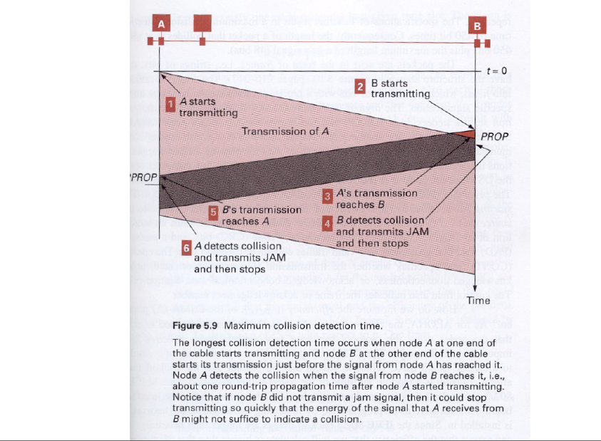
T_p = max prop delay between 2 nodes in LAN t_trans = time to transmit max-size frame
efficiency =
efficiency goes to 1
- as Tp goes to 0
- as ttrans goes to infinity better performance than ALOHA: and simple, cheap, decentralized!
Scheduling
- by time, frequency or both: cellular (and latest)
- polling from central site (Bluetooth)
random access
- Aloha (still in use)
- CSMA: carrier sensing
- Collision detection easy in some technologies (wire), hard in others (wireless). CSMA/CD used in Ethernet
Can you compare them?
MAC Address
MAC addresses are administered by the IEEE.
Manufacturers buys portion of MAC address space.
- 48-bit MAC address (for most LANs) burned in NIC ROM, also sometimes software settable
- hexadecimal (base 16) notation
- (each “numeral” represents 4 bits)
- e.g.: 1A-2F-BB-76-09-AD
how to determine interface’s MAC address, knowing its IP address?
- There’s an ARP table
IP/MAC address mappings for some LAN nodes.
A wants to send datagram to B
- B’s MAC address not in A’s ARP table, so A uses ARP to find B’s MAC address
IMPORTANT
Unlike IP addresses which are not portable (it depends on IP subnet to which node is attached), MAC addresses are, which means that we can move interface from one LAN to another.
ARP Protocol
ARP table: each node (host, router) on LAN has table
- IP/MAC address mappings for some LAN nodes:
< IP address; MAC address; TTL> - TTL (Time To Live): time after which address mapping will be forgotten (typically 20 min)
example: A wants to send datagram to B
- B’s MAC address not in A’s ARP table, so A uses ARP to find B’s MAC address
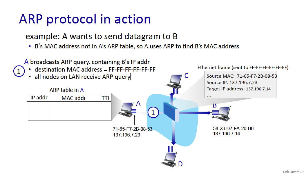
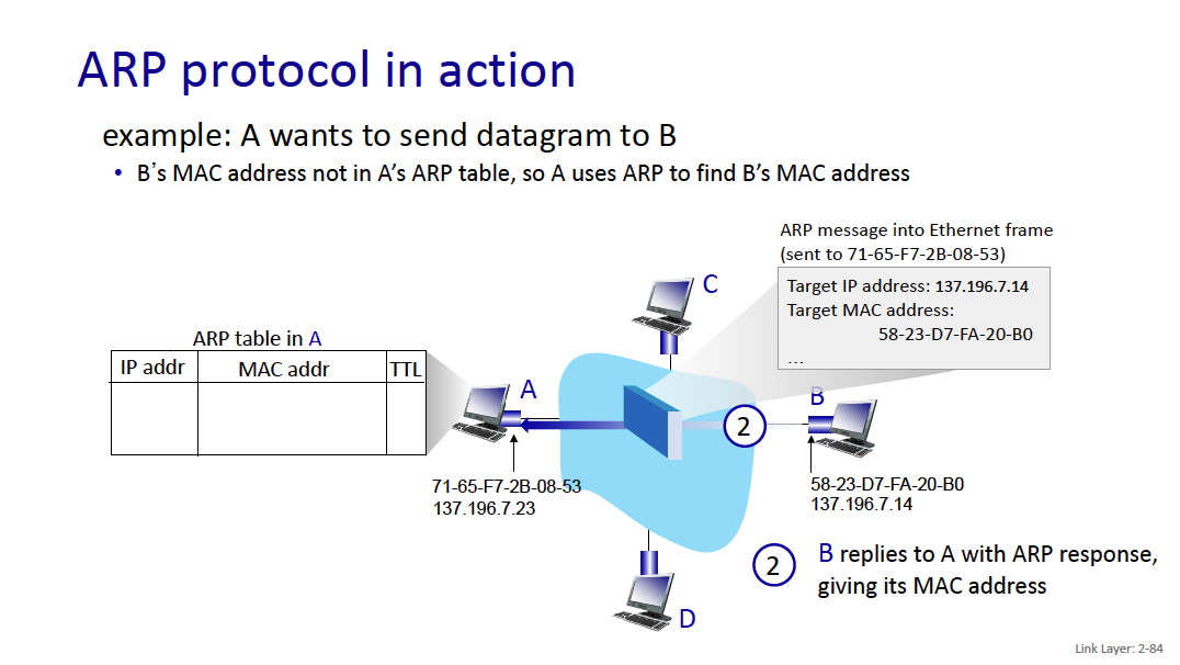
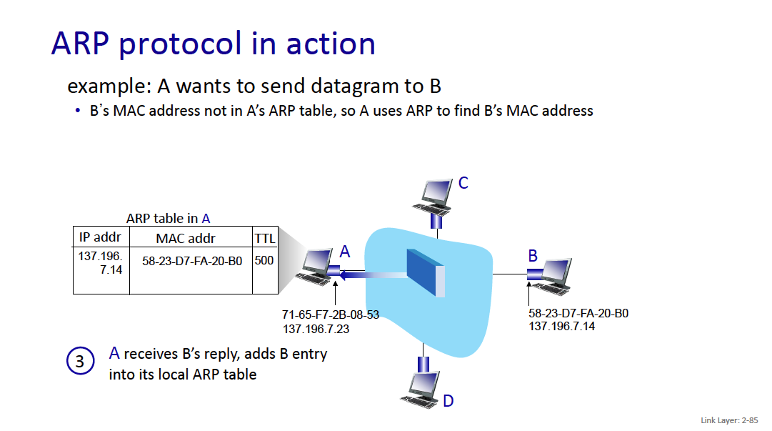
The routing mechanism is also super interesting.
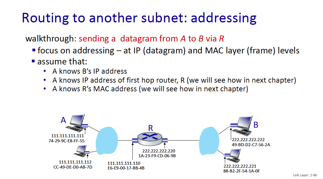
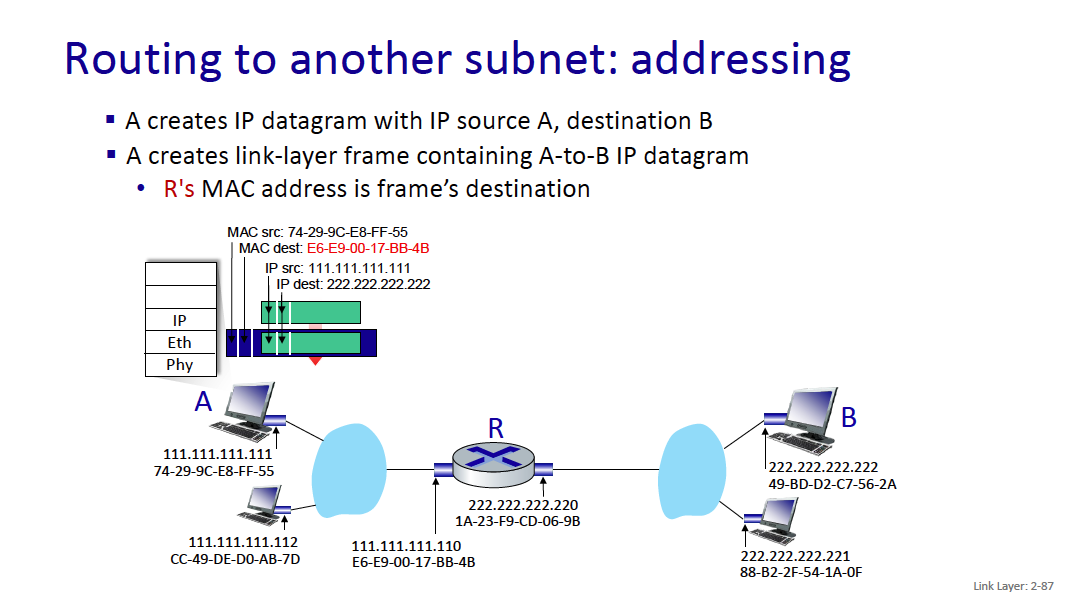
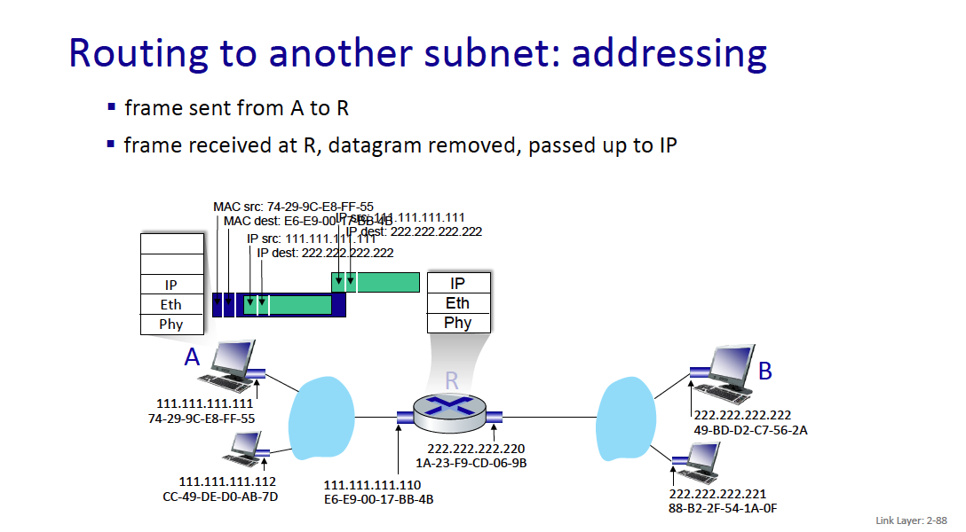
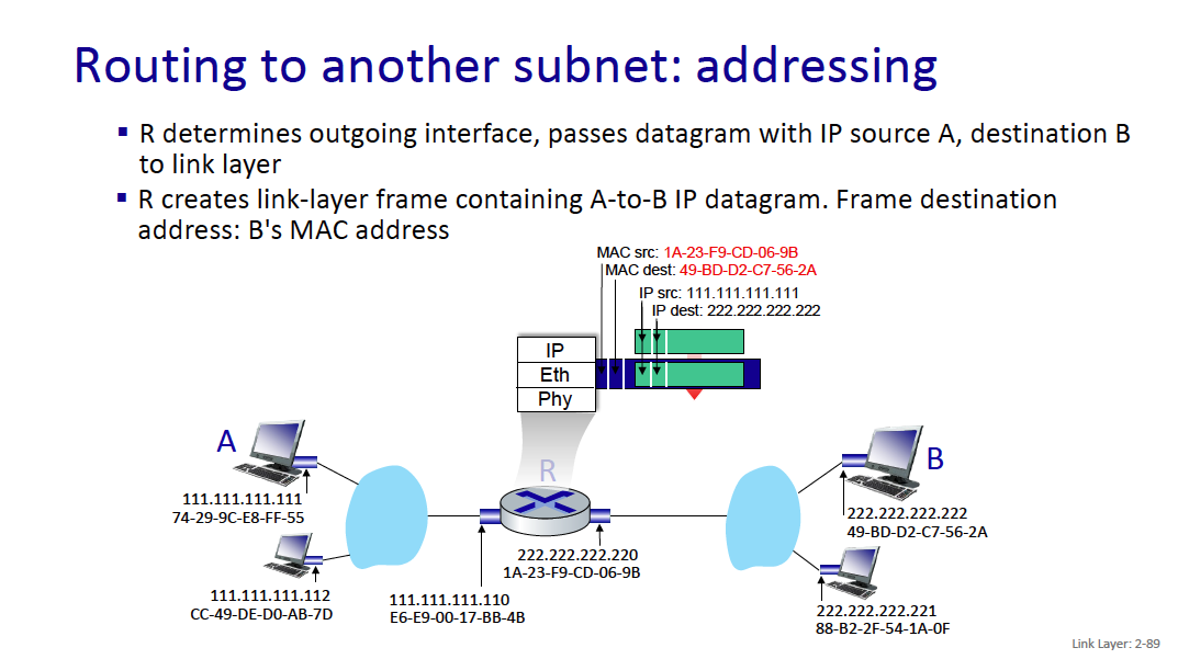
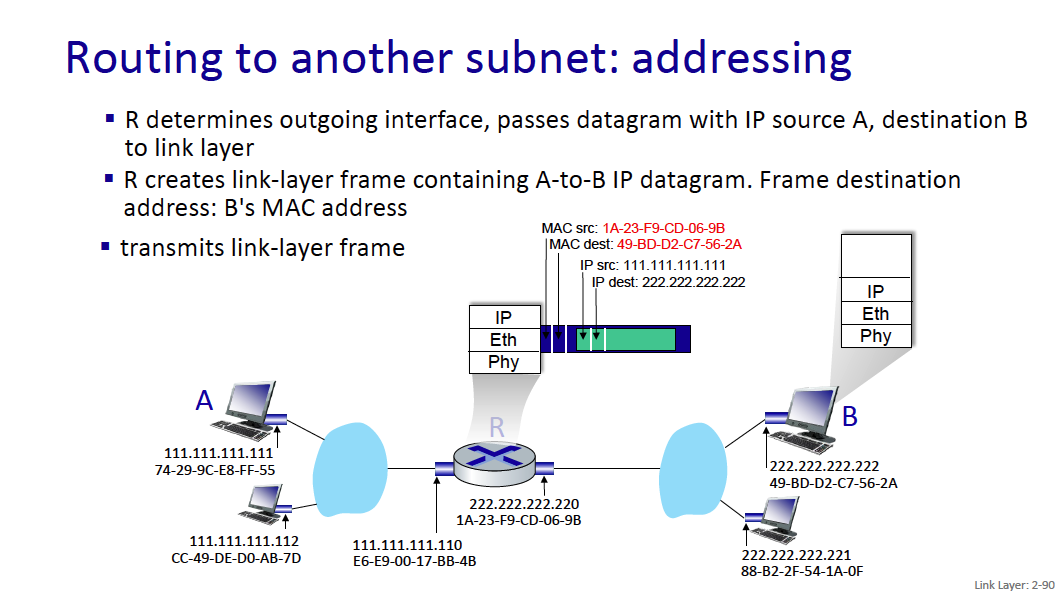
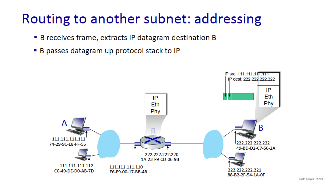
When I go to google.com, idk the MAC address of it?? So how does this work
Because it is an IP address outside of the current network, your computer will send the traffic to the gateway (generally 192.168.1.1), and you’ll get the MAC address of the gateway (through the ARP Table). Then, the gateway will do some logic and forward whatever.
- Your machine only needs to know the MAC address of devices on the local network (like your router). Once the packet leaves your network, routers only care about IP addresses.
MAC addresses are used for local (same network) communications, while IP addresses are used for routing across different networks.
Ethernet
This is quite interesting.
When Ethernet first got started, it was a bus, which would results in lots of collisions, and each computer needed to coordinate with each other. Seems like a real pain. And then mechanisms to check collisions (ALOHA or CSMA)
bus: popular through mid 90s
- all nodes in same collision domain (can collide with each other)
- bus: coaxial cable switched
- switched: prevails today
- active link-layer 2 switch in center
- each “spoke” runs a (separate) Ethernet protocol (nodes do NOT collide with each other)

Ethernet Frame Structure
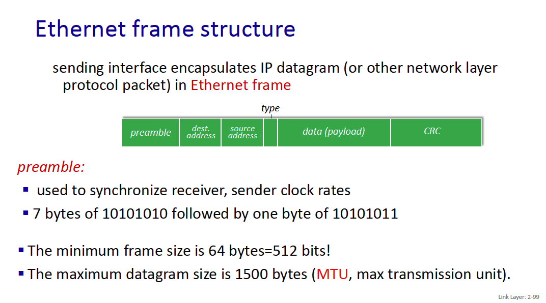
The maximum datagram size is 1500 bytes (MTU, max transmission unit).
preamble:
- used to synchronize receiver, sender clock rates
- 7 bytes of 10101010 followed by one byte of 10101011
addresses: 6 byte source, destination MAC addresses
- if adapter receives frame with matching destination address, or with broadcast address (e.g., ARP frame), it passes data in frame to network layer protocol or ARP
- otherwise, adapter discards frame
type: indicates higher layer protocol
- mostly IP but others possible, e.g., Novell IPX, AppleTalk
- a special value for ARP
- used to demultiplex up at receiver CRC: cyclic redundancy check (4 bytes)
- error detected: frame is dropped
The maximum datagram size is 1500 bytes (MTU, max transmission unit).
Switch is a link-layer device: takes an active role
- stores, forwards Ethernet frames
- examines incoming frame’s MAC address, selectively forwards frame to one-or-more outgoing links, uses CSMA/CD to access each link
- transparent: hosts unaware of presence of switches
- plug-and-play, self-learning
- switches do not need to be configured
entry:
-
(MAC address of host, interface to reach host, time stamp)
-
looks like a routing table!
-
connectionless: no handshaking between sending and receiving NICs
-
unreliable: receiving NIC doesn’t send ACKs or NAKs to sending NIC
-
data in dropped frames recovered only if initial sender uses higher layer rdt (e.g., TCP), otherwise dropped data lost
-
Ethernet’s MAC protocol: unslotted CSMA/CD with binary backoff
Switches have multiple transmissions.
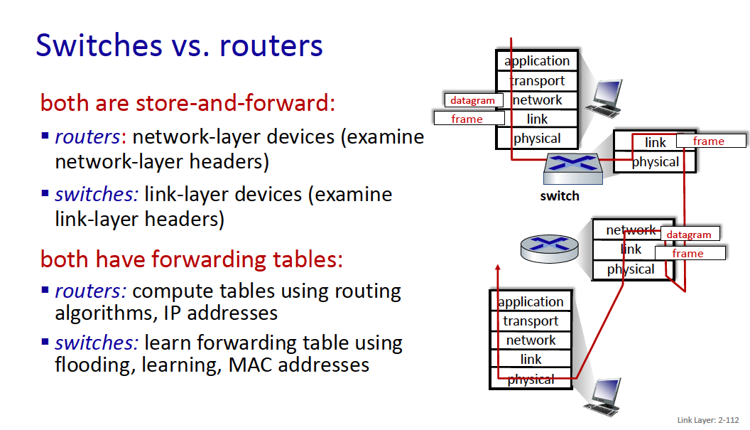
Switches vs. routers
- Routers are network-layer devices
- Switches are link-layer devices
Both have forwarding tables
- routers: compute tables using routing algorithms, IP addresses
- switches: learn forwarding table using flooding, learning, MAC addresses
- What do they mean by flooding here?
Chapter 3: Network Layer
There are 2 planes at the network layer (i remember this from Ericsson!!):
- Data Plane
- Control Plane
The data plane: the Internet Protocol
- IPv4: datagram format
- IPv4: addressing
- IPv4: network address translation
- middleboxes
- IPv6
What’s inside a router? →The control plane: ICMP, Routing
transport segment from sending to receiving host
- sender: encapsulates segments into datagrams, passes to link layer
- receiver: delivers segments to transport layer protocol
Network layer protocols in every Internet device: hosts, routers
What do routers do?
- examines header fields in all IP datagrams passing through it
- moves datagrams from input interfaces to output interfaces to transfer datagrams along end-end path
Network-layer functions
- forwarding: move packets from a router’s input link to appropriate router output link: very common task (for all datagrams) done very fast (a few nanoseconds)
- routing: network-wide process that determines route taken by packets from source to destination to fill forwarding tables (done in the background and not triggered by datagrams arrivals, time-scale is few seconds) > - routing algorithms
A modern view of the network layer breaks it down into the data plane and control plane.
Data plane:
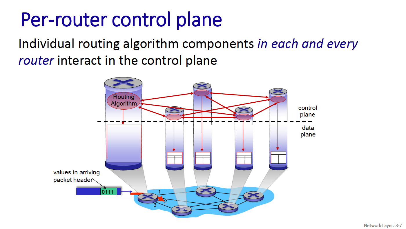
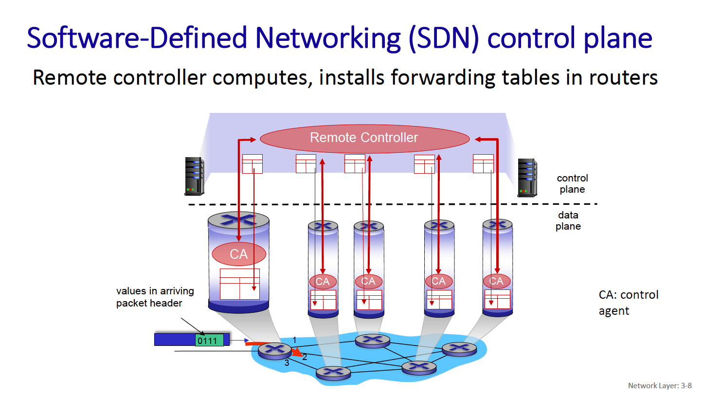
- local, per-router function
- determines how datagram arriving on router input interface is forwarded to router output interface
Control Plane
- network-wide logic
- determines how datagram is routed among routers along end-end path from source host to destination host
- two control-plane approaches:
- traditional routing algorithms: implemented in routers (both planes are implemented monolithically within a router)
- software-defined networking (SDN): explicitly separate the two planes by implementing the control plane as a service in (remote) servers
IP Addresses
The Data Plane: Internet Protocol (IP): from v4 to v6
- Connectionless (datagram-based)
- Best-effort delivery (unreliable service)
- packets are lost
- packets are delivered out of order
- packets can be delayed for a long time
- A common packet format for IPv4 (fragmentation is the mechanism that makes this format work over networks with different MTUs). A new packet format for IPv6 (no fragmentation).
- A global addressing scheme (one for v4 and one for v6) for identifying all hosts (ARP is the mechanism that makes this addressing scheme work over networks with different physical (MAC) addressing schemes).
- A sister protocol that performs error reporting and enables signaling between routers: ICMP (v4, v6).
ipv4 and ipv6
Main difference between ipv4 and ipv6?
- ipv4 uses 32-bit address format
- ipv6 uses 128-bit address format
Ipv4 and Ipv6
- initial motivation: 32-bit IPv4 address space would be completely allocated
Additional motivations:
- speed processing/forwarding: 40-byte fixed length header
- enable different network-layer treatment of “flows”
- enables better mobility management
Headers for Ipv4
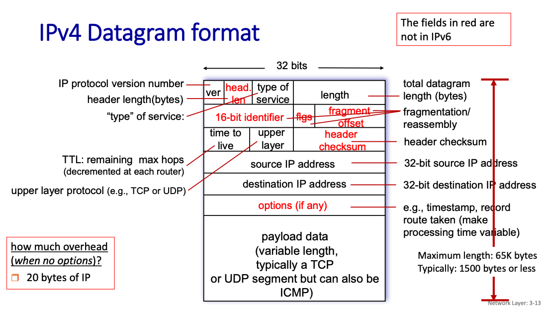
Mandatory IPv4 Header (20 bytes):
- Version
- can be ipv4 or ipv6
- Header Length
- Type of Service
- 8 bits that specifies the quality of service that the packet should receive as it traverses a network
- Total Length
- Identification (16-bit identifier)
- Flags
- Fragment Offset
- Time to Live (TTL)
- Protocol
- Header Checksum
- Source IP Address
- Destination IP Address
Why do we need header length, when length is already part of the datagram?
Without the Header Length, the receiver wouldn’t know where the header ends and the payload begins if the header includes optional fields.
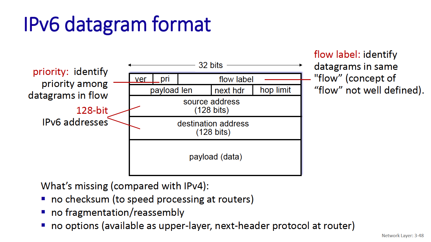
So you’lkl notice 3 new things:
- Flow label
- next header
- hop limit
Flow Label
- a 20-bit field designed to support efficient handling of packets belonging to the same “flow,” enabling features such as Quality of Service (QoS) and improved routing.
Next header
- IPv6 introduces the concept of extension headers for features such as routing, fragmentation, or security (e.g., IPsec).
Hop Limit
- The Hop Limit field in IPv6 determines how many hops (routers) the packet can traverse before being discarded. It replaces the Time to Live (TTL) field in IPv4 but with a simpler and more intuitive meaning:
IPv4 Fragmentation
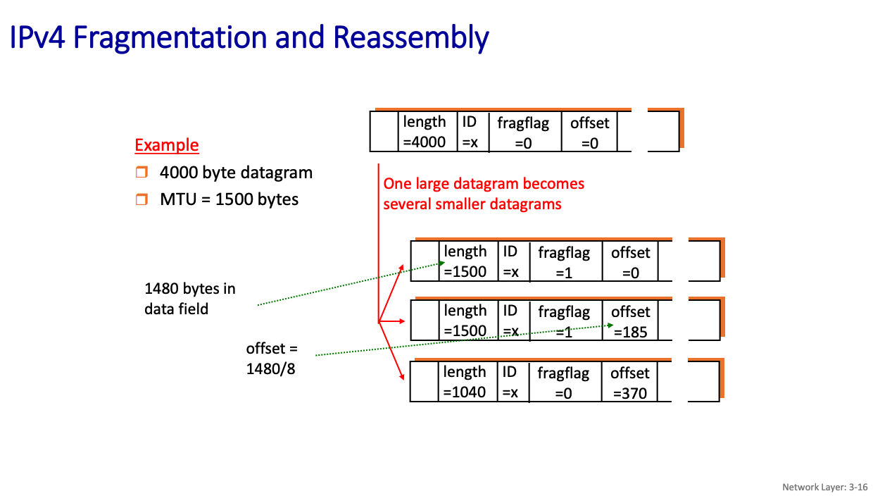
- Link layer protocols have MTU (max. transfer unit size)
- largest possible data size in a frame.
- different link types, different MTUs (Ethernet: 1500 bytes, WiFi: ≤ 2312 bytes (often configured at less))
large IP datagram divided (“fragmented”) within net
- one datagram becomes several datagrams
- “reassembled” only at final destination
- A fragment can be re-fragmented later
- IP header bits used to identify, order related fragment
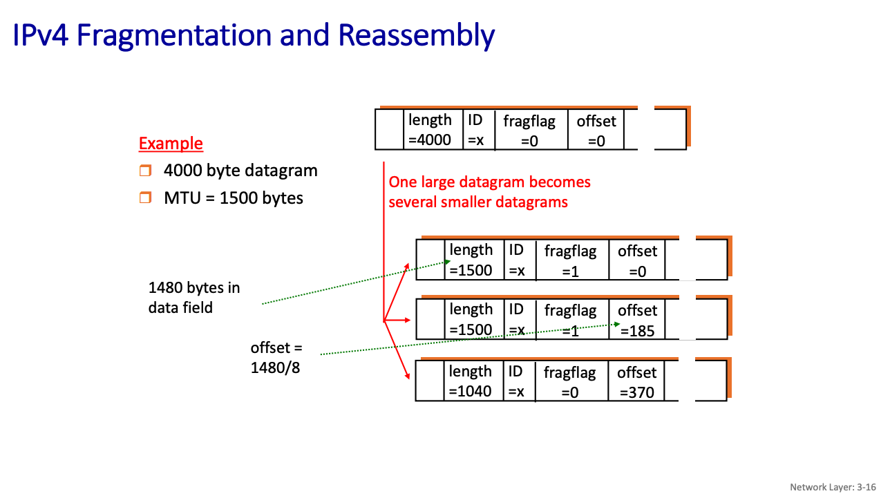
- Notice that 20 bytes are used for the header, and then the rest is the data field
Why is there an offset?
- The offset field in the IPv4 header specifies the position of a fragment’s data within the original datagram.
The offset in IPv4 fragmentation is measured in 8-byte (64-bit) blocks, not individual bytes. This design choice provides several benefits:
IP Addressing
Okay, so how does DHCP work?
DHCP
DHCP overview: a client server protocol using UDP, a network function implemented as an application protocol (NOT network protocol).
- host broadcasts DHCP discover msg
- DHCP server responds with DHCP offer msg
- host requests IP address: DHCP request msg
- DHCP server sends address: DHCP ack msg
DHCP: Dynamic Host Configuration Protocol goal: host dynamically obtains IP address from network server when it “joins” network (plug and play)
- can renew its lease on address in use
- allows reuse of addresses (only holds address while connected/on)
- support for users who join/leave network
How does host get an IP address? 2 ways:
- hard-coded by sysadmin in config file (e.g., /etc/rc.config in UNIX)
- DHCP: Dynamic Host Configuration Protocol: dynamically get address from a server
- “plug-and-play”
DHCP overview: a client server protocol using UDP, a network function implemented as an application protocol !!!
- host broadcasts DHCP discover msg
- DHCP server responds with DHCP offer msg
- host requests IP address: DHCP request msg
- DHCP server sends address: DHCP ack msg
https://en.wikipedia.org/wiki/Dynamic_Host_Configuration_Protocol
The DHCP client broadcasts a DHCPDISCOVER message on the network subnet using the destination address 255.255.255.255 (limited broadcast).
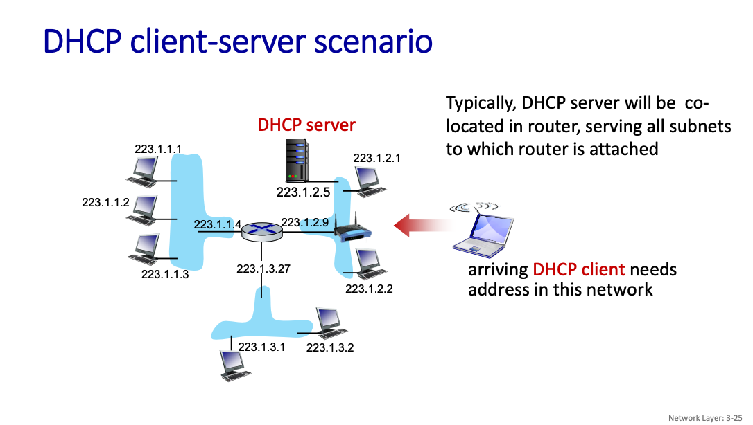
So is the router the thing that is doing the DHCP?
Default Behavior: Most home and small-office routers come with a built-in DHCP server enabled by default. Dynamic IP Allocation: The router assigns an IP address from a predefined range (e.g., 192.168.0.2–192.168.0.254) to devices when they connect to the network.
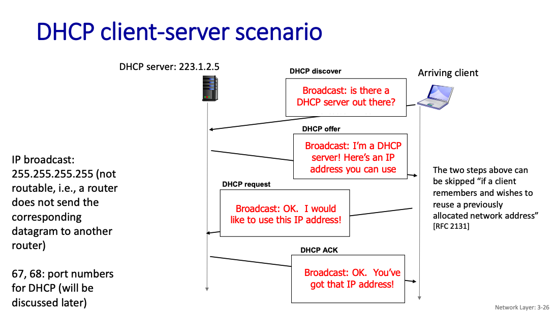
What DHCP returns
DHCP will return more than just allocated IP address on subnet:
- address of first-hop router for client
- name and IP address of DNS server (to be discussed later)
- address prefix (indicating network versus host portion of address)
DHCP is a network function implemented as an application protocol (on top of UDP)
- So it exists at the APPLICATION layer
In the real world, how does this work?
how does a network get subnet part of IP address?
It gets allocated portion of its provider ISP’s address space. Look up ICANN: Internet Corporation for Assigned Names and Numbers http://www.icann.org/
- allocates IP addresses, through 5 regional registries (RRs) (who may then allocate to local registries)
- manages DNS (see later)
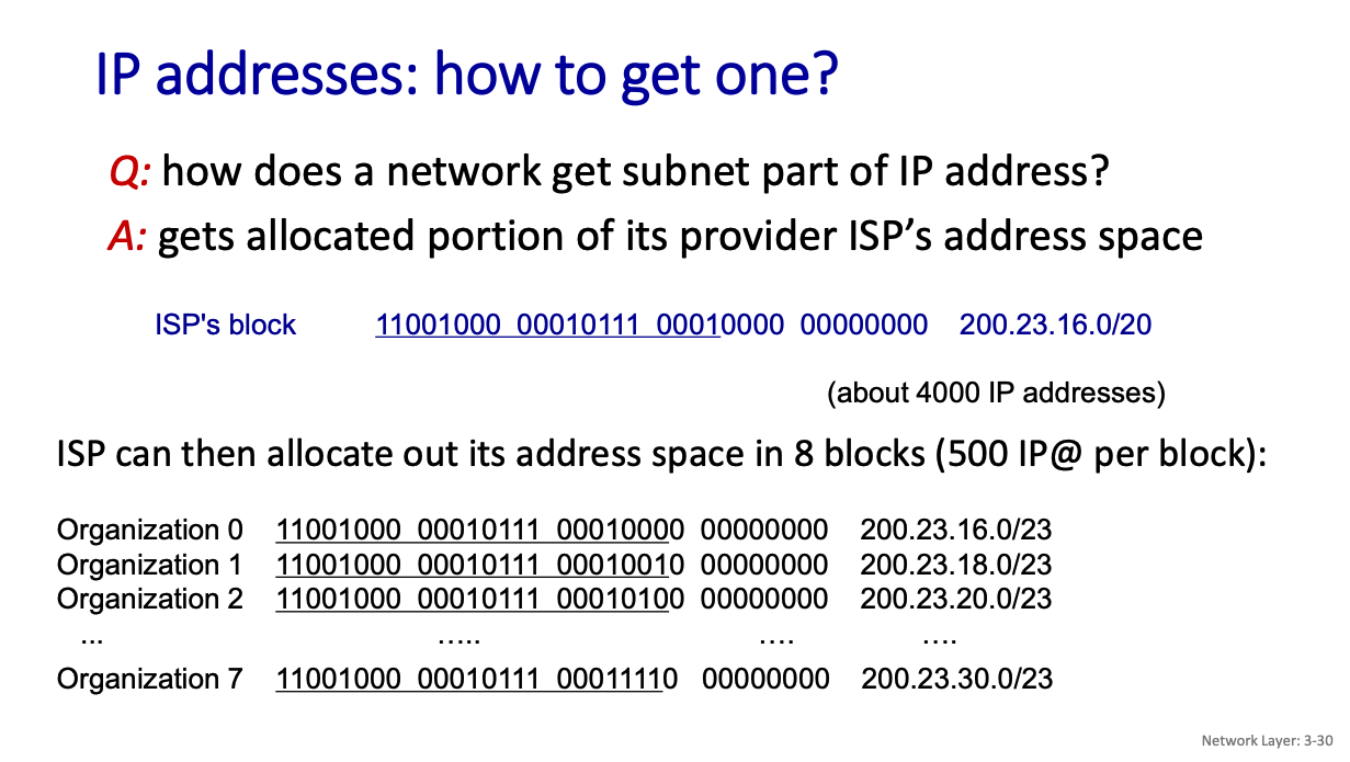
ISPs use DHCP (Dynamic Host Configuration Protocol) to dynamically assign public IPs to customers.
- Each customer gets an IP from a shared pool, which may change over time (e.g., after modem/router reboots).
- Subnet masks are often /32 or /30, depending on whether you’re using one public-facing device or multiple
NAT: Network address translation
When you are on your local network, you get something like 192.168.1.200, not the address that your ISP assigned to you. How does that work? This is where Network Address Translation comes in.
NAT: all devices in local network share just one IPv4 address as far as outside world is concerned.
Motivation: Limiting the number of addresses given to a home or small office network, re-using IP addresses in a smart way (we usually cannot)
All devices in home or small office network have 32-bit addresses in a “private” IP address space (10/8, 172.16/12, 192.168/16 prefixes). These addresses are not routable outside the home or small office and hence can be reused as much as we want.
Advantages
- range of addresses not needed from ISP: just one IP address for all devices
- can change addresses of devices in local network without notifying outside world
- can change ISP without changing addresses of devices in local network
- devices inside local net not explicitly addressable, visible by outside world (a security plus)
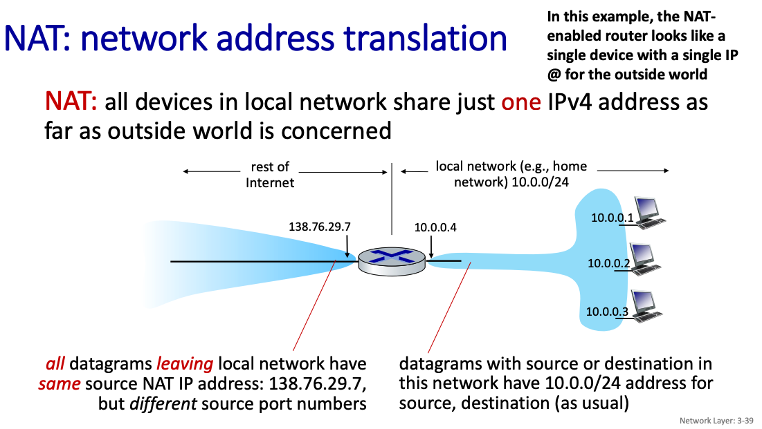
So then how can we talk to a particular device?
- all datagrams leaving local network have same source NAT IP address: 138.76.29.7, but different source port number
datagrams with source or destination in this network have 10.0.0/24 address for source, destination (as usual)
Mapping from:
- NAT IP address - source IP address
- NAT port - source port
implementation: NAT router must (transparently):
- outgoing datagrams: replace (source IP address, port #) of every outgoing datagram to (NAT IP address, new port #)
- remote clients/servers will respond using (NAT IP address, new port #) as destination address
- remember (in NAT translation table) every (source IP address, port #) to (NAT IP address, new port #) translation pair
- incoming datagrams: replace (NAT IP address, new port #) in destination fields of every incoming datagram with corresponding (source IP address, port #) stored in NAT table
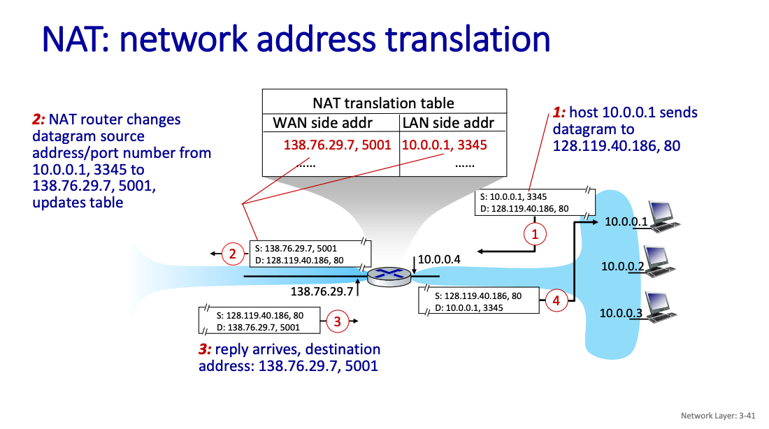
The NAT maintains a 16-bit port-number field:
- 60,000 simultaneous connections with a single public IP address!
The router will keep NAT entries in the translation table for a configurable length of time. For TCP connections, the default timeout period is 24 hours. Because UDP is not connection based, the default timeout period is much shorter—only 5 minutes.
- NAT has been controversial:
- routers “should” only process up to layer 3
- address “shortage” should be solved by IPv6
- violates end-to-end argument (port # manipulation by network-layer device)
- NAT traversal: what if client wants to connect to server behind NAT?
- But NAT is here to stay:
- extensively used in home and institutional nets, 4G/5G cellular nets
Does it map each device on the local network to a global IP?
No, to differentiate between multiple devices and their connections, NAT leverages the concept of ports.
Tunneling
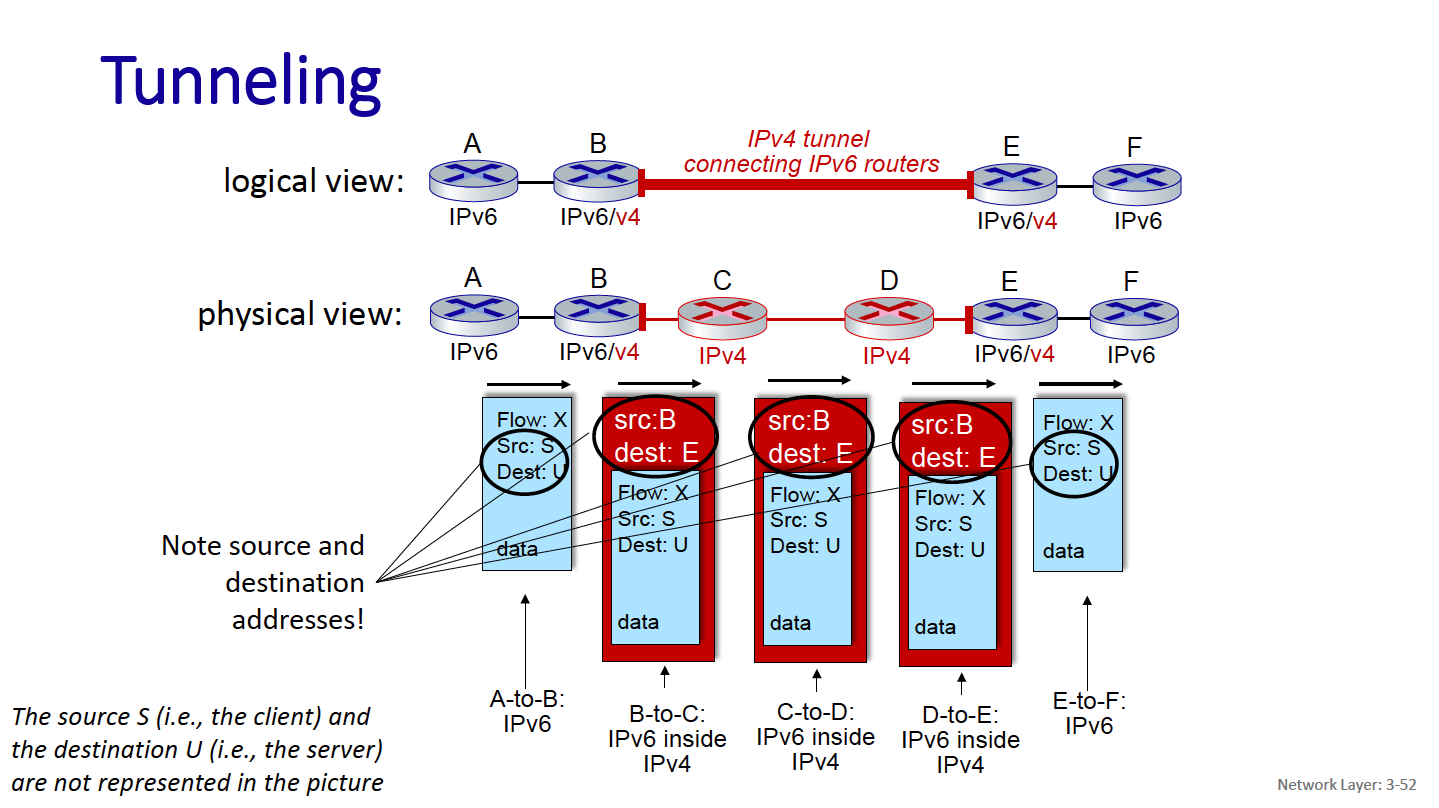
How will network operate with mixed IPv4 and IPv6 routers?
Through tunneling: IPv6 datagram carried as payload in IPv4 datagram among IPv4 routers (“packet within a packet”)
- tunneling used extensively in other contexts (4G/5G)

Subnets
Addressing scheme: CIDR: Classless InterDomain Routing (pronounced “cider”)
- IP addresses have structure: a subnet part and a host part
- subnet portion of address of arbitrary length
- address format: a.b.c.d/x, where x, the prefix, is the # bits in subnet portion of address
What is CIDR?
Classless Inter-Domain Routing (CIDR) is an IP address allocation method that improves data routing efficiency on the internet.
What’s a subnet?
A subnet is a set of interfaces that have IP addresses with the same prefix and same subnet portion. They can physically reach each other without passing through an intervening router.
Subnetting is done by extending the subnet mask beyond the default mask (for classful addressing, e.g., Class A, B, C).
- For example, dividing a
192.168.1.0/24network into smaller subnets like192.168.1.0/26,192.168.1.64/26, etc.
Subnetting is primarily about splitting a given network into smaller parts. It is often used in internal or private networks.
CIDR uses variable-length subnet masking (VLSM) to allocate IP addresses in a non-classful manner.
- Instead of being limited to predefined classes (e.g., Class A
/8, Class B/16, etc.), CIDR allows any prefix length, like/10,/15,/27, etc. - This prevents IP address wastage and allows ISPs to allocate only as many IPs as needed.
For example, an ISP can advertise 192.168.0.0/16 to cover both 192.168.0.0/24 and 192.168.1.0/24.
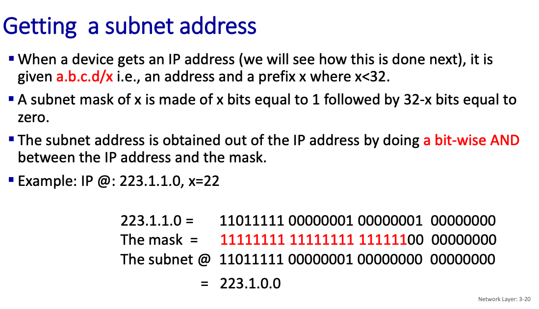
I’ve done this before through WATonomous!
Why is subnetting important?
- If it’s in the same subnet, you don’t need it to to go the router. You can just directly route it to the destination (i.e., in a frame where the destination MAC @ is the one of the destination, if this MAC @ is not known, use ARP)
Router Architecture
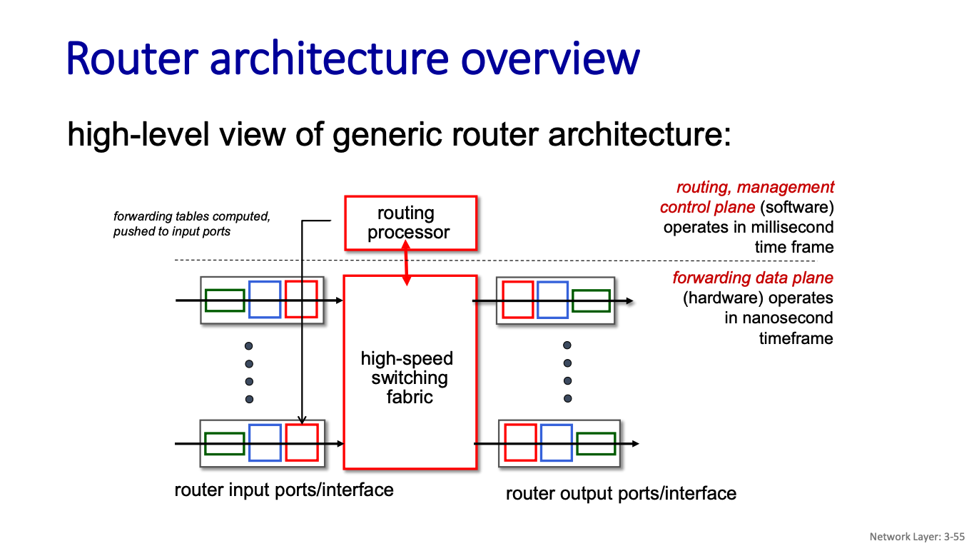
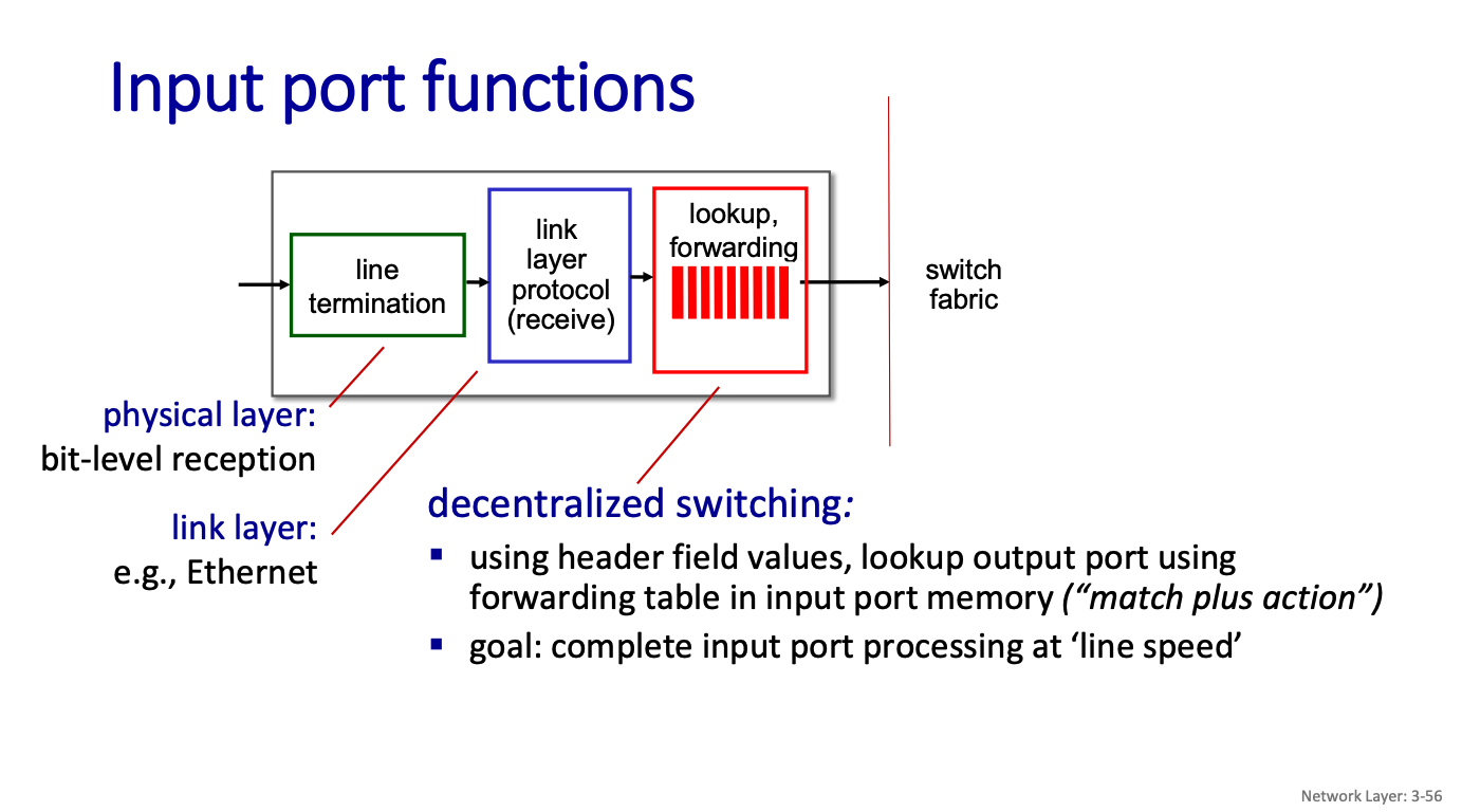
Switching
There are three major types of switching fabrics:
- memory
- bus
- interconnection network

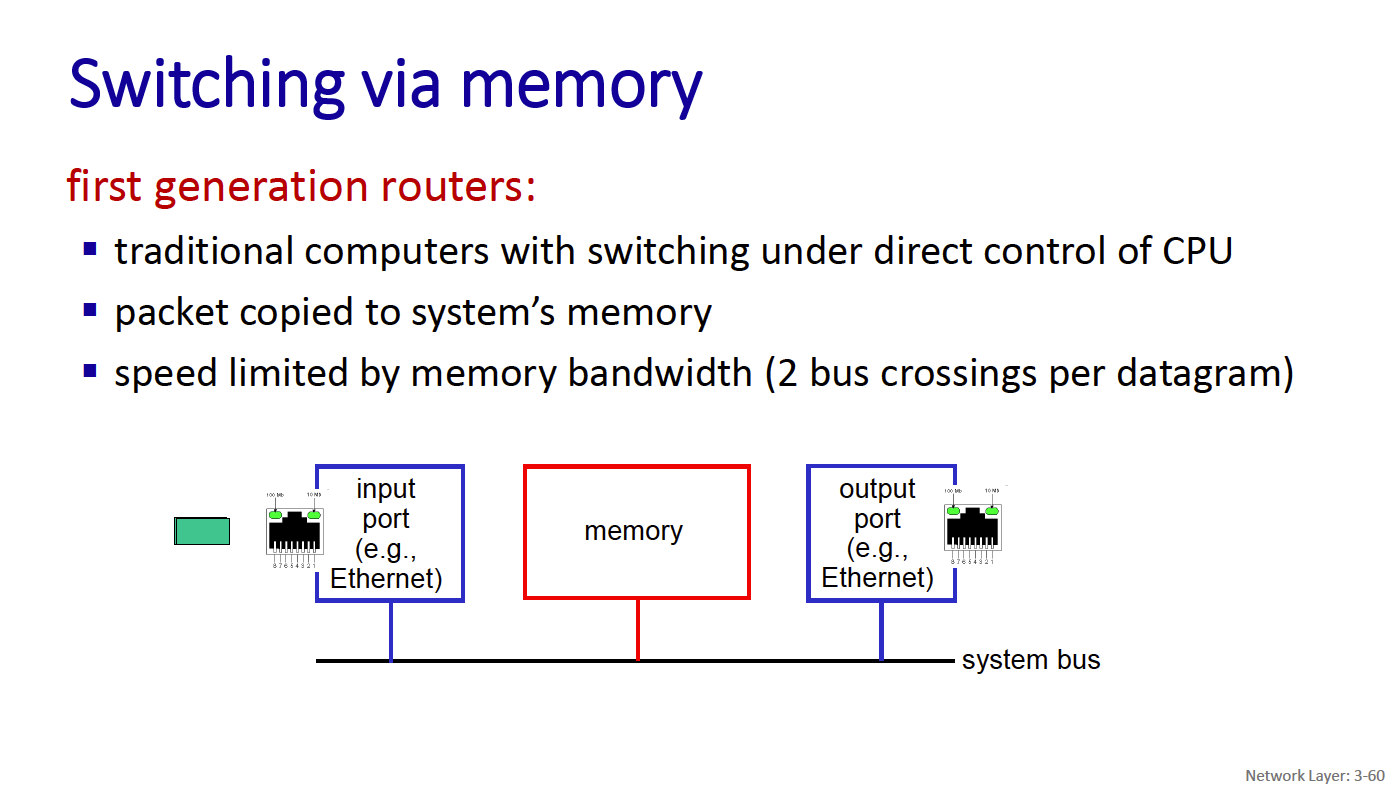
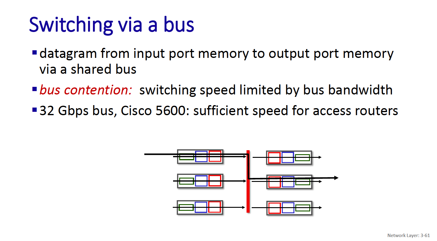
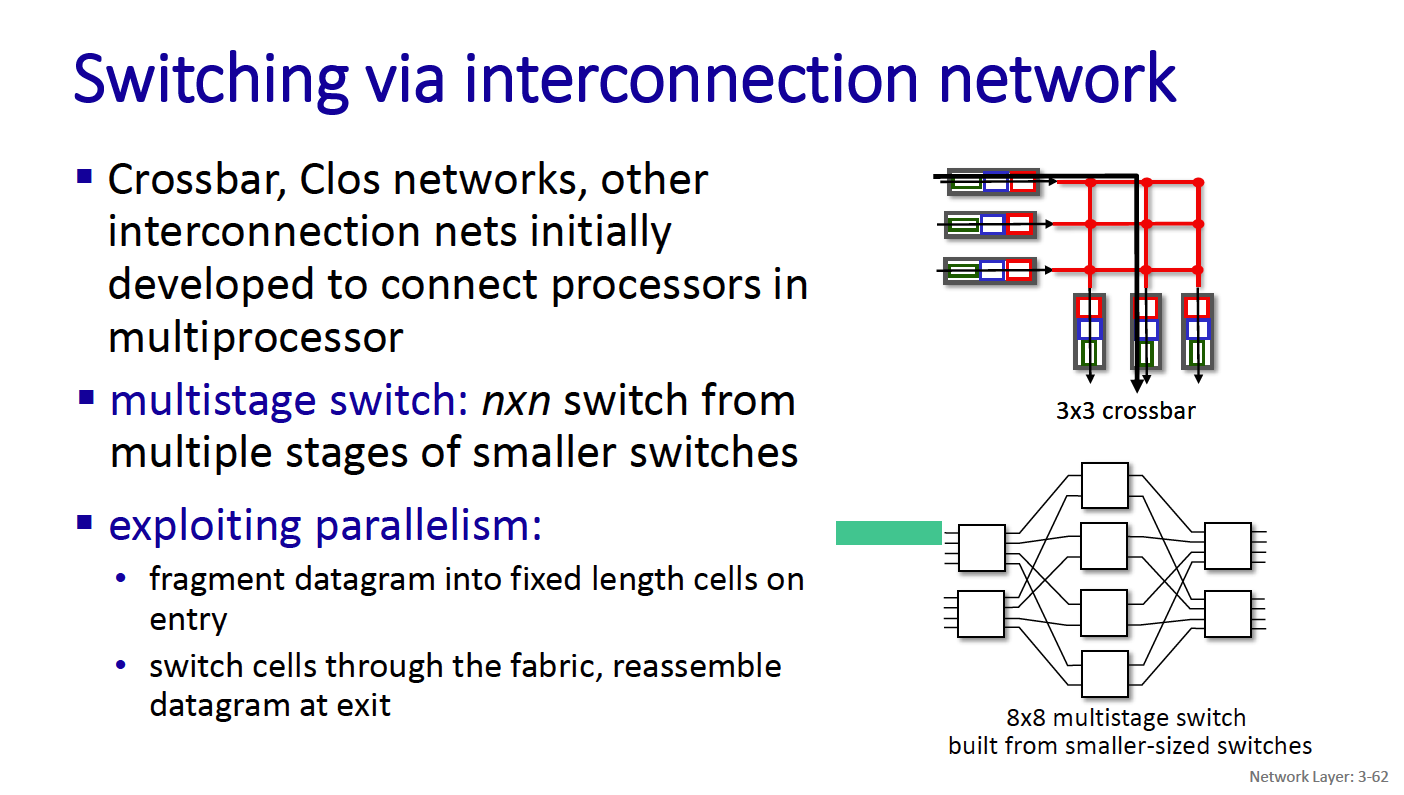
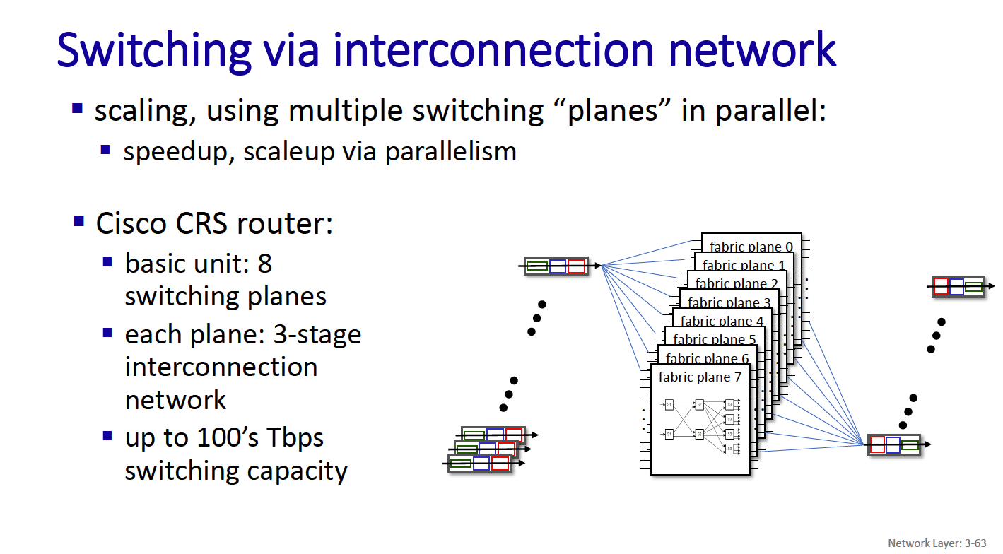
- CRS is the carrier routing system
The Control Plane: ICMP (Internet Control Message Protocol)
Best-effort does not mean careless. IP attempts to avoid errors and report problems when they occur. IP does not
- Introduce errors
- Ignore all errors
Errors detected
- Corrupted header bits: Header checksum
- Illegal addresses: Routing tables
- Routing loops: Time-To-Live (TTL) field
- Fragment loss: Timeout
ICMP is a separate protocol for
- Errors reporting
- Information
Required part of IP (architecturally just above IP (layer 3.5)) Sends error message to original source.
The Control Plane: Routing protocols
Routing protocol goal: determine “good” paths (equivalently, routes), from sending hosts to receiving host, through network of routers.
- By “good”, we mean: least “cost”, “fastest”, “least congested”
Routing is a “top-10” networking challenge!
The Internet approach to scalable routing is to aggregate routers into regions known as “autonomous systems” (AS)
An autonomous system (AS) refers to a collection of IP networks and routers under the control of a single organization or administrative entity that presents a common routing policy to the internet.
Intra-AS Routing → Interior Gateway Protocols (IGP) Inter-AS Routing → Border Gateway Protocol
There are 2 main families of routing algorithms:
- In distance vector algorithms, nodes send information about their distances from all other nodes to their neighbours.
- In link state algorithms, nodes send information about their distances from their neighbours to all other nodes
Example of calculation for link-state algorithm
- Essentially, always pick the node with the shortest distance
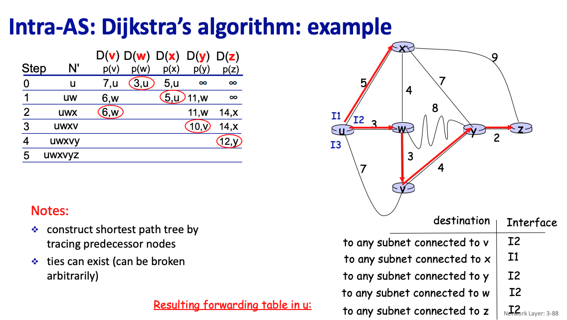
For distance, you can use the convention , for node and iteration .
Most common IGPs:
- RIP: Routing Information Protocol
- OSPF: Open Shortest Path First
- IGRP: Interior Gateway Routing Protocol (Cisco proprietary)
A routing table in the context of shortest-path routing protocols (such as RIP or OSPF) lists the best next-hop node for reaching every possible destination in the network.
Chapter 4: Transport Layer
- Connectionless transport: UDP
- Connection-oriented transport: TCP
I don't understand the difference between network and transport layer?
Transport vs. network layer services and protocols:
- network layer: logical communication between hosts
- transport layer : logical communication between processes
- relies on, enhances, network layer services
An analogy
12 kids in Ann’s house sending letters to 12 kids in Bill’s house:
- hosts = houses
- processes = kids
- app messages = letters in envelopes
Transport services and protocols provide logical communication between application processes and running on different hosts.
Two main transport protocols:
- TCP (transport control protocol) → reliable, in-order unicast delivery between 2 processes
- UDP (user datagram protocol) → unreliable, unordered delivery
identifier includes both IP address and port numbers associated with process on host. example port numbers:
- HTTP server: 80
- mail server: 25
We need ports because there can be many processes running on the same host. We need to know how to reach that particular process.
What ports do servers and clients pick?
- Server has a well-known port (e.g., port 80)
- Between 0 and 1023
- Client picks an unused ephemeral (i.e., temporary) port
- Between 1024 and 65535
To send HTTP message to gaia.cs.umass.edu web server:
• IP address: 128.119.245.12
• port number: 80
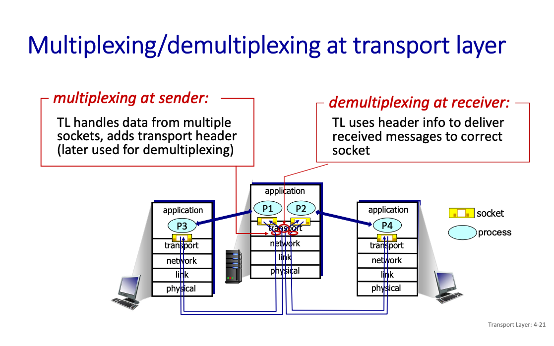
So what is demultiplexing...?
Demultiplexing is delivering data (in the form of transport-layer segments) to the correct application or process running on a host. It’s routing it to the correct port.
What is happening in demultiplexing?
- Receiving IP Datagrams:
- Your host (computer, server, etc.) receives data packets called IP datagrams over the network.
- Each datagram contains two important pieces of addressing information:
- Source IP Address: Where the packet is coming from.
- Destination IP Address: Where the packet is headed (your device).
- Inside the Datagram:
- Each datagram carries one transport-layer segment. This segment is the payload of the datagram.
- The segment includes:
- Source Port Number: Identifies the sender’s specific application or service (e.g., a web browser or game client).
- Destination Port Number: Identifies the receiving application or service on your host.
With UDP, connectionless socket
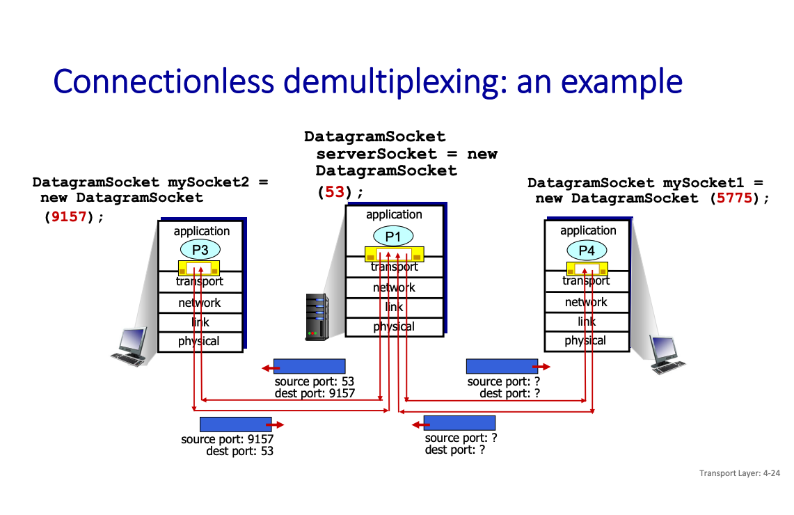
Connectionless: each UDP segment handled independently of others UDP socket identified by a pair: (IP address, port number)
A process using UDP in a client will create a socket with its IP address and an ephemeral port number (for the return)
Will send its segment to a UDP socket in server defined by (Server IP@, permanent port number)
When host receives UDP segment:
- checks destination port number in segment
- directs UDP segment to socket with that port number
IP/UDP datagrams/segments with same destination port # but different source IP addresses and/or source port numbers directed to same socket at receiving host.
Socket programming with TCP
client must contact server
- server process must first be running
- server must have created socket (door) that welcomes clientʼs contact
client contacts server by:
- Creating TCP socket, specifying IP address, port number of server process
- when client creates socket: client TCP establishes connection to server TCP
- when contacted by client, server TCP creates new socket for server process to communicate with that particular client • allows server to talk with multiple clients
TCP provides reliable, in-order byte-stream transfer (“pipe”) between client and server.
TCP socket identified by 4-tuple:
- source IP address
- source port number
- dest IP address
- dest port number
The difference
In TCP, we create a socket for a particular client, which is why TCP is identified using also the source IP and port number. In contrast, for UDP, it’s client agnostic, because we don’t maintain the connection.
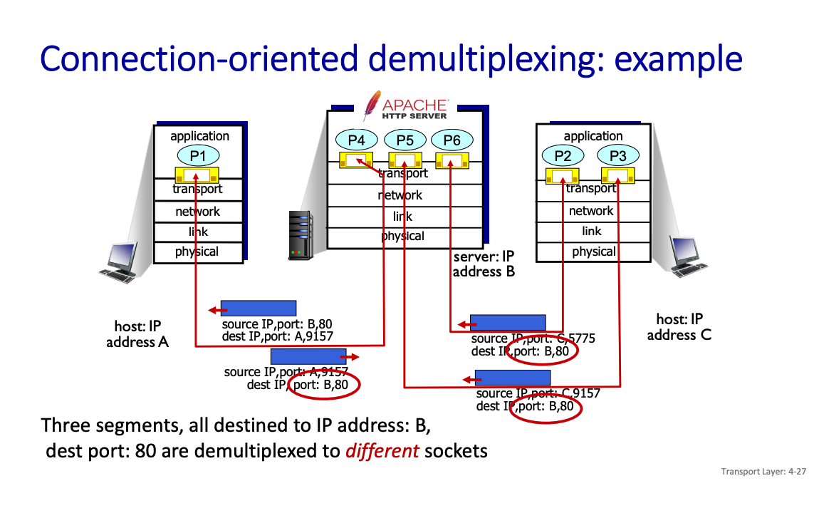
UDP: demultiplexing using destination port number (only) TCP: demultiplexing using 4-tuple: source and destination IP addresses, and port numbers
More on UDP
“best effort” service, UDP segments may be:
- lost
- delivered out-of-order to app
connectionless:
- no handshaking between UDP sender, receiver
- each UDP segment handled independently of others
What do we mean by handshaking?
We mean establishing a formal connection before sending data.
Why does UDP exist?
no connection establishment (which can add RTT delay)
- simple: no connection state at sender, receiver
- small header size
- no congestion control
- UDP can blast away as fast as desired!
- can function in the face of congestion
Some use cases of UDP:
- streaming multimedia apps (loss tolerant, rate sensitive)
- DNS
- SNMP (management protocol)
- HTTP/3
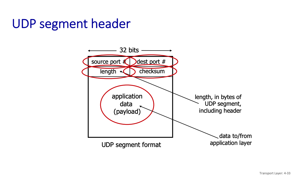
UDP checksum sender:
- treat contents of UDP segment (including UDP header fields and IP addresses) as sequence of 16-bit integers
- checksum: addition (one’s complement sum) of segment content (2 sequences of 16 bits at a time)
- checksum value put into UDP checksum field
receiver:
- compute the sum of all 16-bit integers incl. checksum
- check if computed checksum equals 1111111111111111
- Not equal - error detected
- Equal - no error detected. But maybe errors nonetheless?
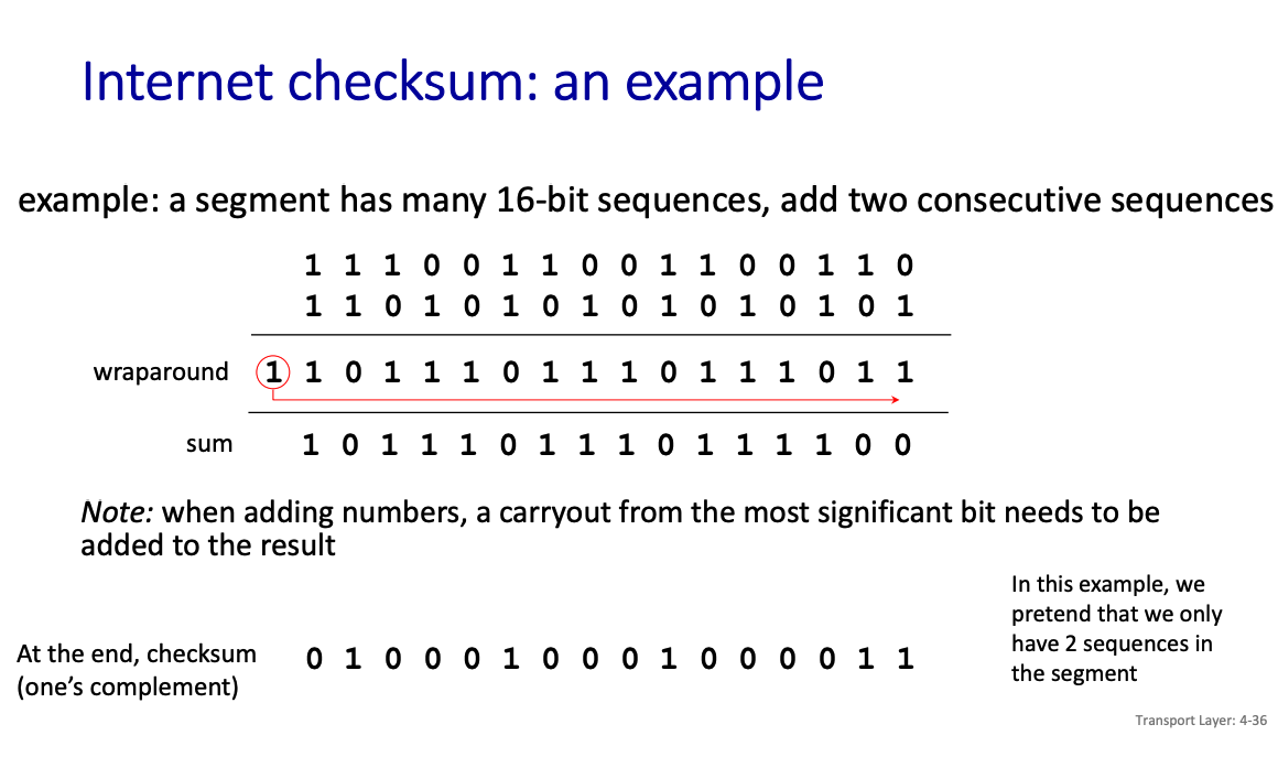
Above is an example
- The sum is in the wraparound row, but since it exceeds the maximum value, that gets wrapped aronud the the final value.
Then, we simply apply One’s Complement.
This checksum is weak protection, because consider the following example
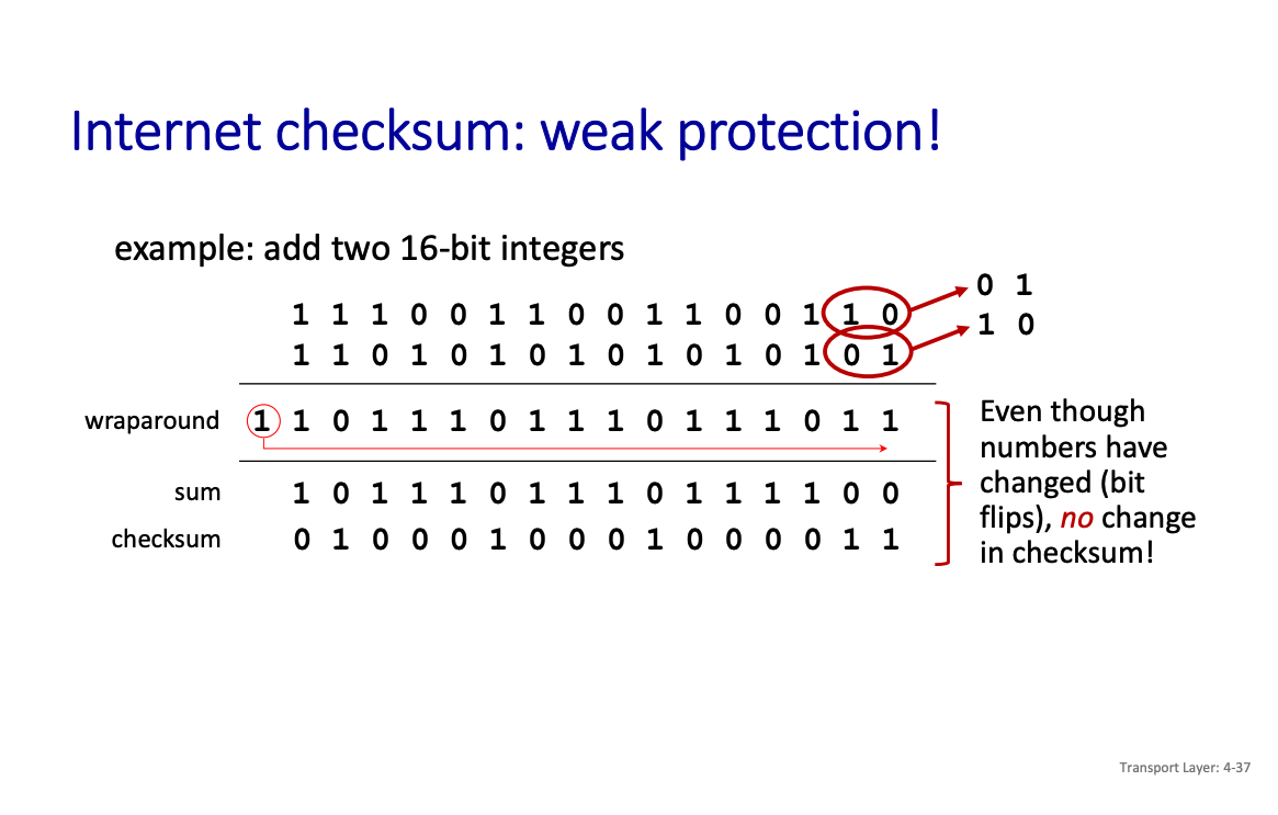
Summary: UDP “no frills” protocol:
- segments may be lost, delivered out of order
- best effort service: “send and hope for the best”
UDP has its plusses:
- no setup/handshaking needed (no RTT incurred)
- Some (limited) help with reliability (checksum)
build additional functionality on top of UDP in application layer (e.g., HTTP/3).
TCP
TCP provides a completely reliable (no data duplication or loss), connection-oriented, full-duplex byte stream transport service that allows two application processes to form a connection, send data in either direction, and then terminate the connection.
Non-trivial because the underlying IP service can lose, re-order, corrupt, delay, fragment, duplicate packets.
TCP provides 3 main functionalities:
- Reliable data transfer (see chapter 2, pipelined retransmission mechanism with two twists: smart acknowledgment management and adaptive window size)
- Congestion control
- Flow Control
TCP is connection-oriented: need to create and close a logical connection, to maintain state
TCP Overview
- point-to-point: one sender, one receiver
- reliable, in-order byte stream: no “message boundaries”
- full duplex data
- bi-directional data flow in same connection
- MSS: maximum segment size
- cumulative ACKs
- pipelining: TCP congestion and flow control set window size
- connection-oriented:
- handshaking (exchange of control messages) initializes sender, receiver states before data exchange
- flow controlled: sender will not overwhelm receiver
TCP Segment Structure
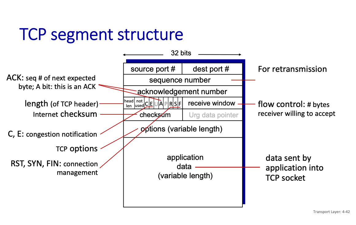
So you see that a TCP segment is a lot more complex.
Doesn't the network layer / link layer handle this as well?
Like we saw this with retransmission??
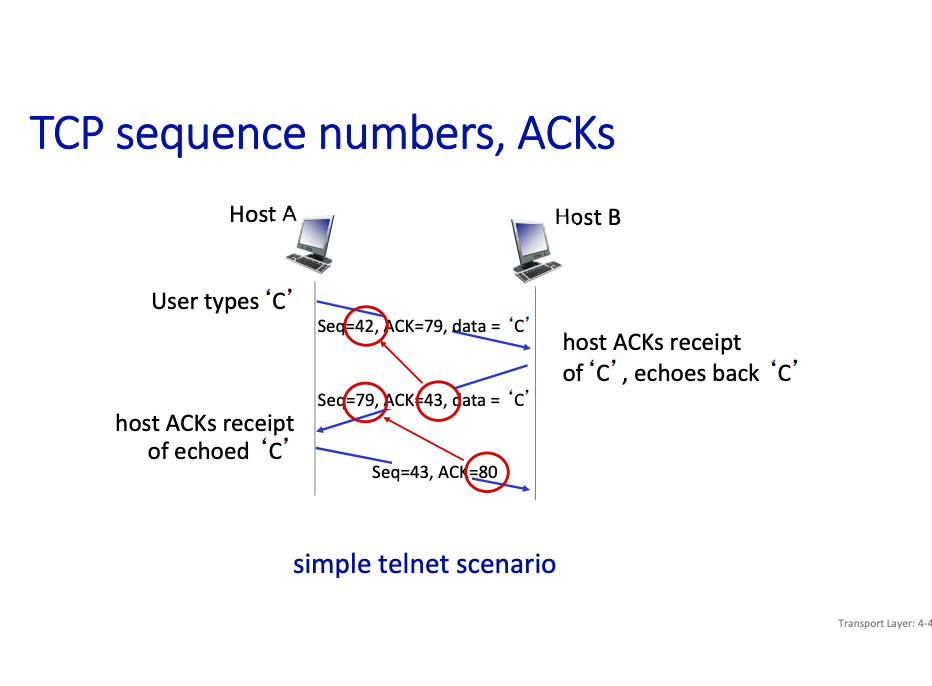
TCP Sequence Numbers
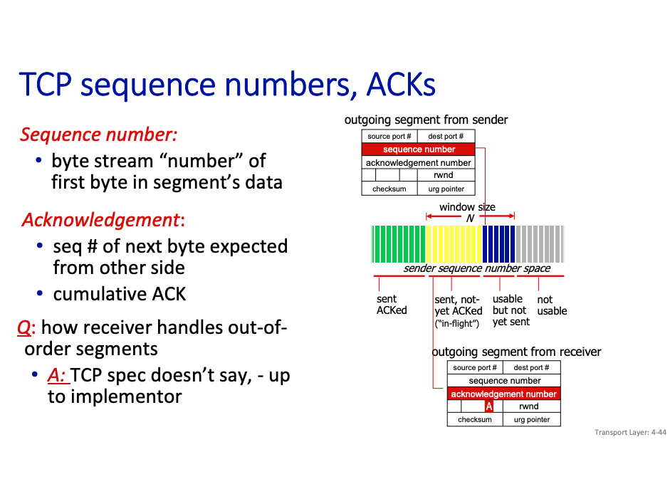
TCP Spec doesn’t specify how to handle out of order. However, for link layer, we know.
TCP Flow Control
TCP Flow Control
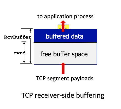
receiver controls sender, so sender won’t overflow receiver’s buffer by transmitting too much, too fast.
TCP flow control
- TCP receiver “advertises” free buffer space in
rwndfield in TCP header RcvBuffersize set via socket options (typical default is 4096 bytes)- many operating systems autoadjust
RcvBuffer - sender limits amount of
unACKed(“in-flight”) data to receivedrwnd - Under normal conditions, receive buffer will not overflow
TCP Connection management and handshaking
Before exchanging data, sender/receiver “handshake”:
- agree to establish connection (each knowing the other willing to establish connection)
- agree on connection parameters (e.g., starting seq numbers)
Why is it a 3-way handshake?
The professor motivates this through showing the 2-way handshake.
Where
- We establish a connection
- We then send over that data
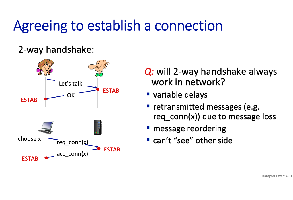
This can work, or not work.
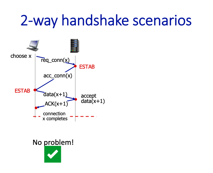
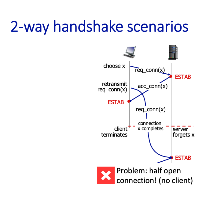
The message exchange, known as 3-way handshake, is necessary and sufficient for:
- Unambiguous, reliable startup
- Unambiguous, graceful shutdown
Still a little confused, see this https://www.baeldung.com/cs/handshakes
We have the flags
- SYN used for startup (synchronize)
- FIN used for shutdown (finish)
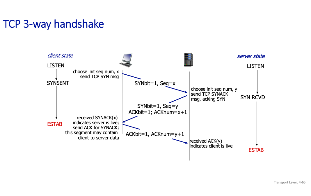
- We use the acknum to be y+1 to make sure that we are referring to the correct thing
So basically, the client waits on the ack, and then sends back an ACK. Only when all 3 are good that it’s good.
2-Way Handshake
In a 2-way handshake, only two steps are involved:
- SYN (Client → Server): The client sends a SYN to the server, indicating it wants to establish a connection.
- ACK (Server → Client): The server responds with an ACK (and possibly its own SYN).
3 way handshaking
There are 3 major steps in 3-way handshaking:
- SYN (Client → Server): The client sends a SYN to initiate the connection.
- SYN-ACK (Server → Client): The server responds with a SYN-ACK, acknowledging the client’s request and sending its own synchronization.
- ACK (Client → Server): The client acknowledges the server’s SYN-ACK, completing the handshake.
Mutual Confirmation: Both sides explicitly confirm receipt of each other’s messages, ensuring synchronization and reliability.
Principles of congestion control
Congestion:
- informally: “too many sources sending too much data too fast for network to handle”
Manifestations:
- long delays (queueing in router buffers)
- packet loss (buffer overflow at routers)
Congestion control is DIFFERENT from flow control
- Congestion control: too many senders, sending too fast
- Flow control: one sender too fast for one receiver
a top-10 problem!

So how do we deal with congestions?
Network-assisted congestion control:
- routers provide direct feedback to sending/receiving hosts with flows passing through congested router
- may indicate congestion level or explicitly set sending rate
- TCP ECN, ATM, DECbit protocols
TCP Congestion Control
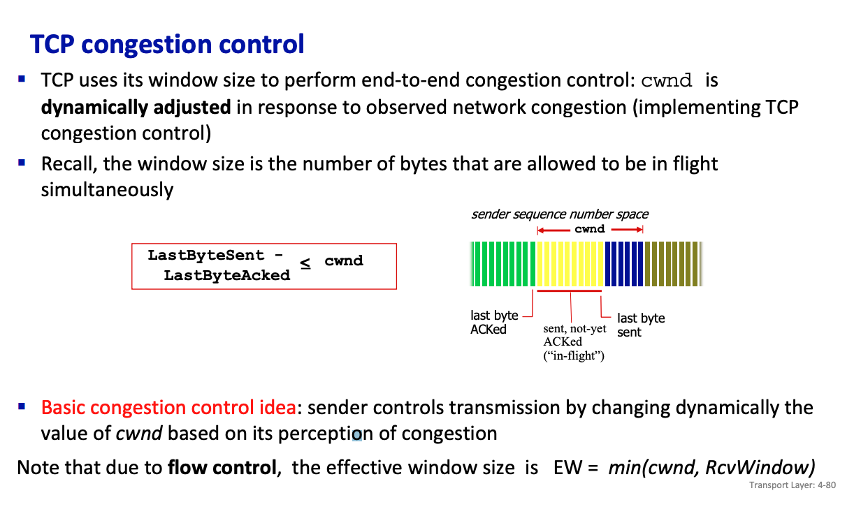
TCP uses its window size to perform end-to-end congestion control: cwnd is dynamically adjusted in response to observed network congestion (implementing TCP congestion control)
- Recall, the window size is the number of bytes that are allowed to be in flight simultaneously
Basic congestion control idea: sender controls transmission by changing dynamically the value of cwnd based on its perception of congestion
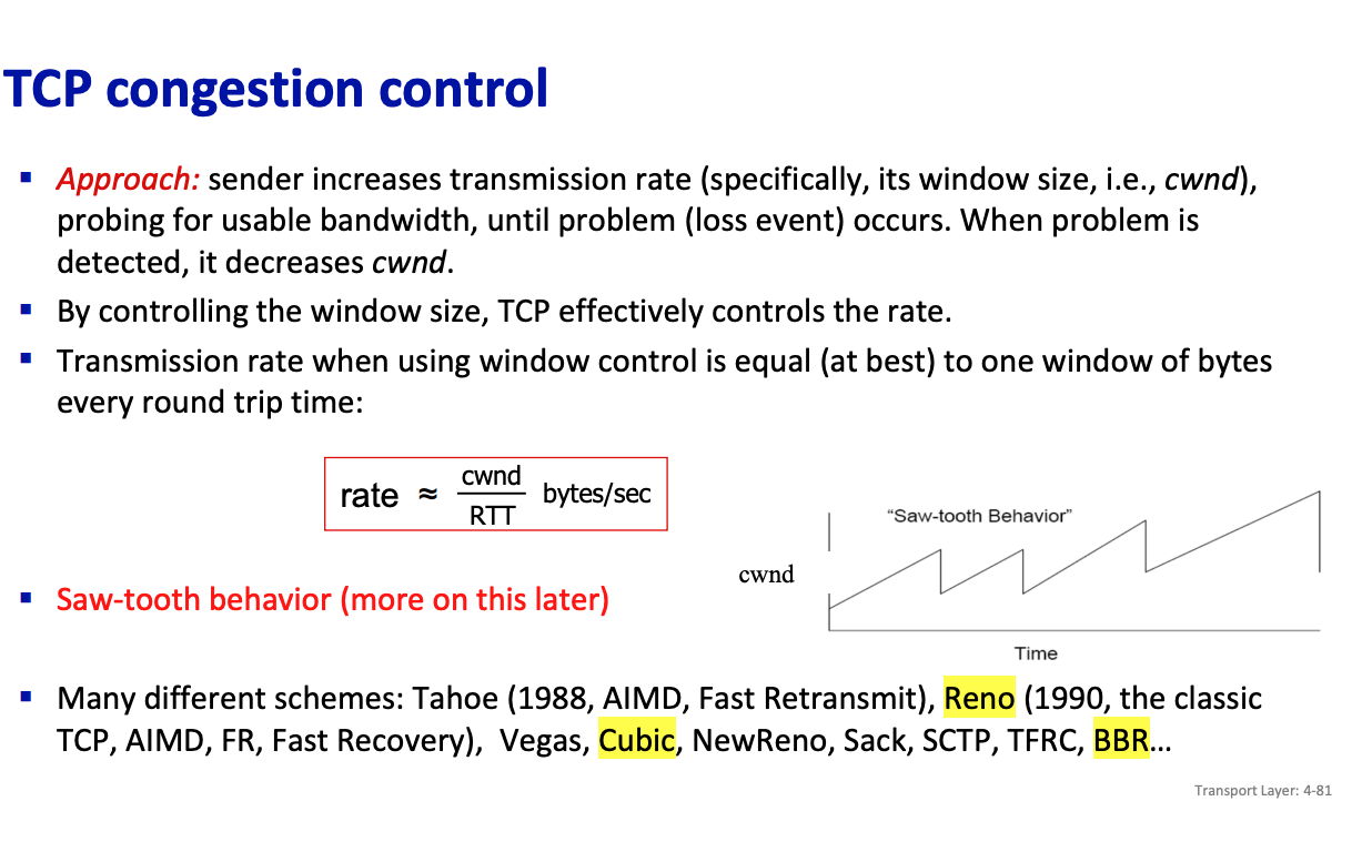
In “Classic” TCP congestion control, there are two “phases”:
- Slow Start
- Congestion Avoidance
important parameters:
cwnd(Congestion Window): The window that limits the amount of data that can be sent into the network before receiving an acknowledgment (ACK)ssthresh(slow start threshold): defines threshold between a slow start phase and a congestion avoidance phase
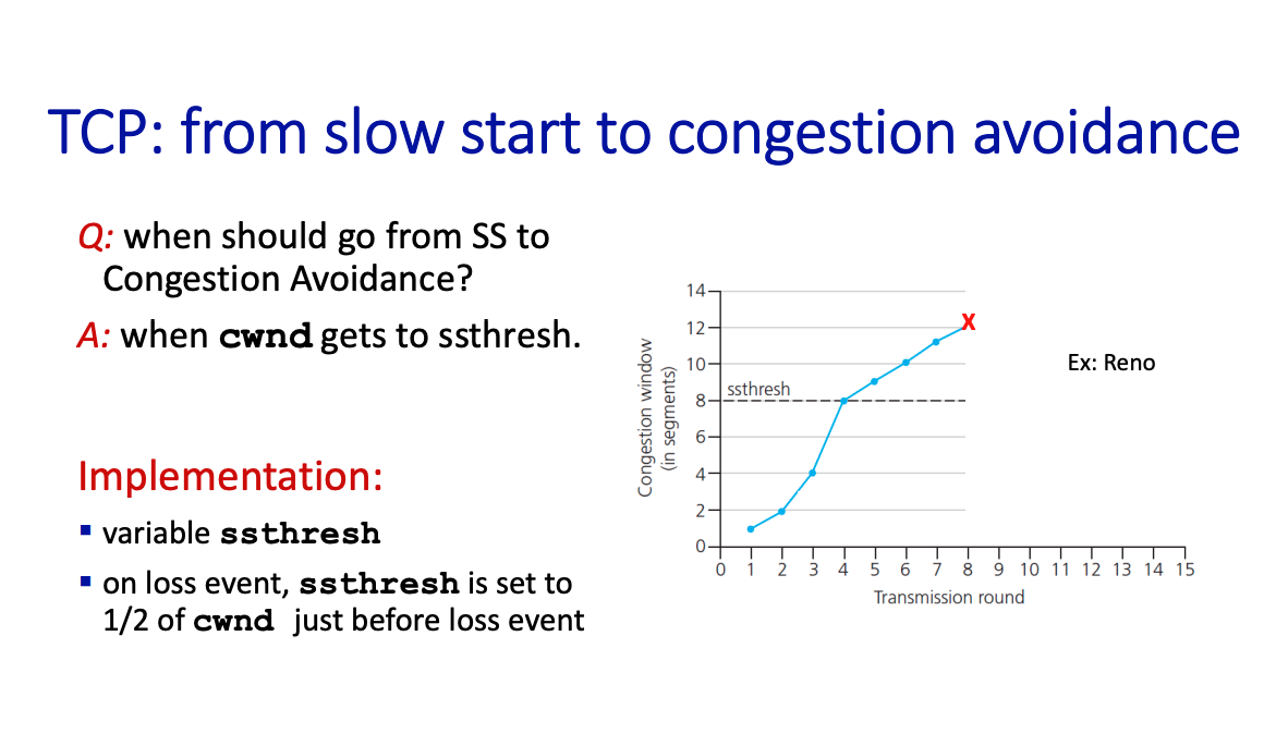
There are two congestion indication mechanisms (i.e., 2 types of loss events):
- 3 Duplicate ACKs - could be due to temporary congestion
- Timeout -more likely due to significant congestion
Basic idea: when congestion occurs decrease the window size, i.e., cwnd.
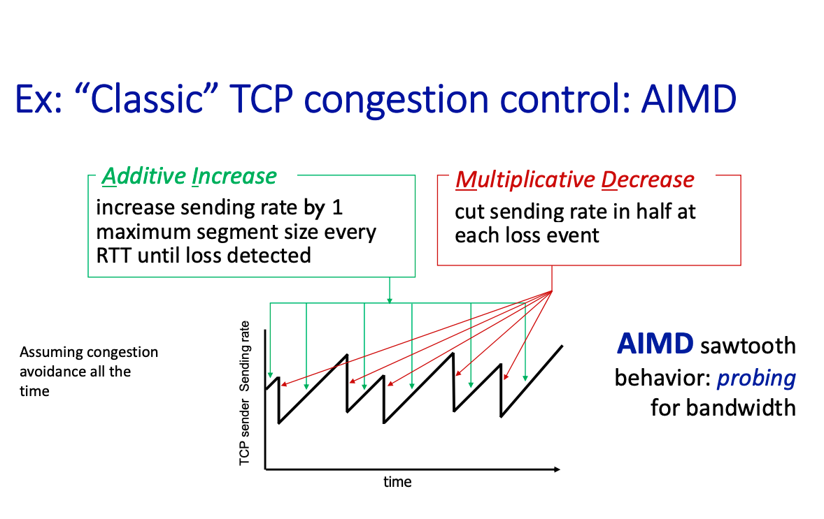
AIMD stands for
- Additive Increase
- Multiplicative decrease (divide sending rate by half)
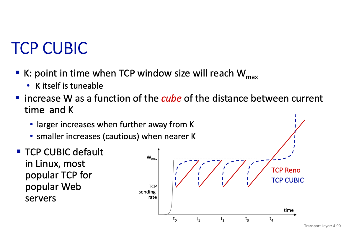
TCP cubic
Chapter 5: Application Layer
There are a few paradigms:
- Client-server
- Peer-to-peer architecture
Client-server paradigm server:
- always-on host
- permanent IP address
- often in data centers, for scaling clients:
- contact, communicate with server
- may be intermittently connected
- may have dynamic IP addresses
- do not communicate directly with each other
- examples: HTTP, IMAP, FTP
Peer-peer architecture
- no always-on server
- arbitrary end systems directly communicate
- peers request service from other peers, provide service in return to other peers
- self scalability – new peers bring new service capacity, as well as new service demands
- peers are intermittently connected and change IP addresses • complex management
- example: P2P file sharing
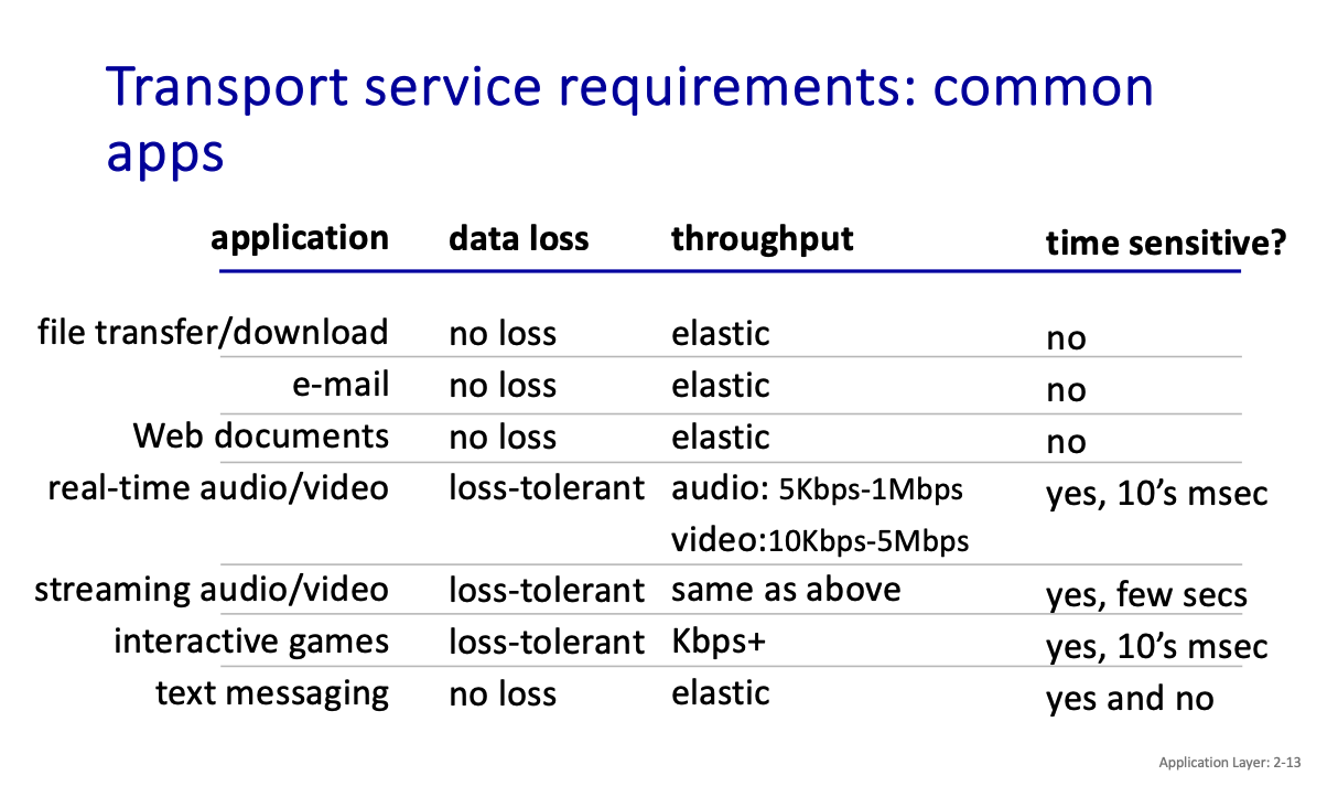
What transport service does an app need?
- Data integrity
- Timing
- Throughput
- Security
Some examples of these requirements and how they are applied:
Socket: door between application process and end-end-transport protocol.
Two socket types for two transport services:
- UDP: unreliable datagram
- TCP: reliable, byte stream-oriented
HTTP: hypertext transfer protocol
HTTP is the web’s application-layer protocol.
HTTP uses TCP:
- client initiates TCP connection (creates socket) to server, port 80
- server accepts TCP connection from client
- HTTP messages (application-layer protocol messages) exchanged between browser (HTTP client) and Web server (HTTP server)
- TCP connection closed
HTTP is “stateless”
- server maintains no information about past client requests
Stateless is NOT the same as non-persistent
- Statelessness is non-retention of data across requests
- Non-Persistence describes connection behavior
HTTP connections: two types
- Non-persistent HTTP
- Persistent HTTP
Non-persistent HTTP
- TCP connection opened
- at most one object sent over TCP connection
- TCP connection closed
In non-persistent HTTP...
Downloading multiple objects required multiple connections…
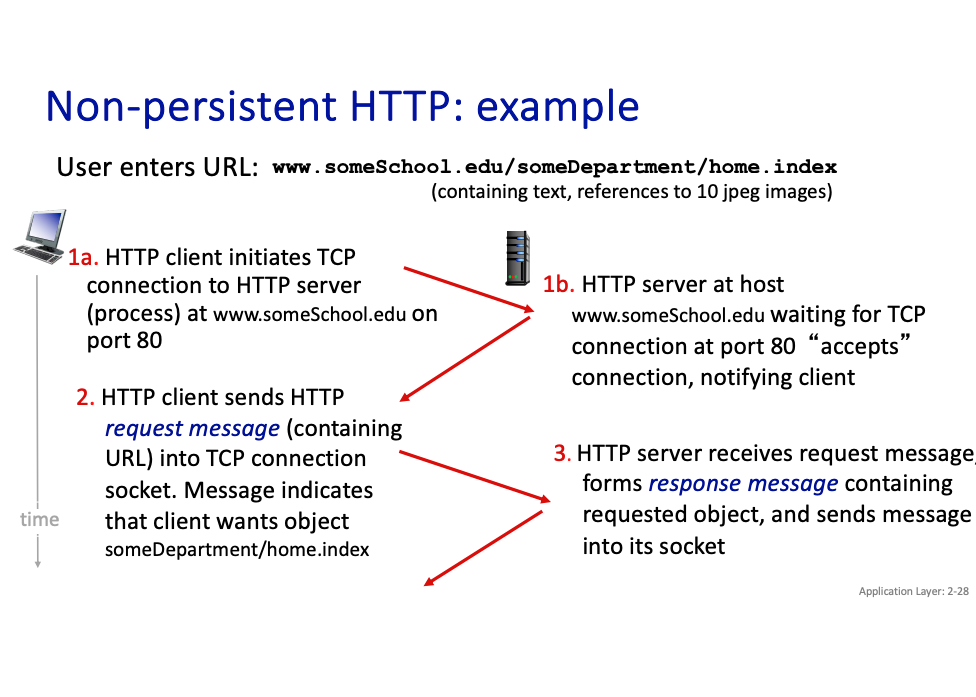
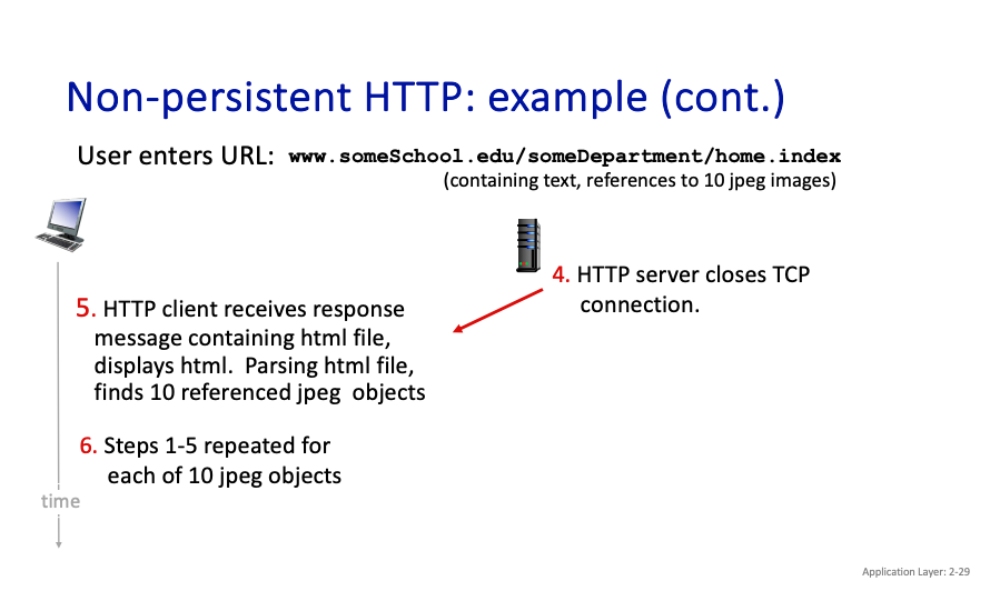
- Is it still a 3-way handshake to establish the connection? Yes. Why isn’t that reflected??? Also, in our calculations, it seems that we do that. So below
Important
In Non-Persistent HTTP: A new TCP connection is established for each HTTP request/response pair. Therefore, the 3-way handshake happens for each request, which can add latency.
Persistent HTTP
- TCP connection opened to a server
- multiple objects can be sent over single TCP connection between client, and that server
- TCP connection closed
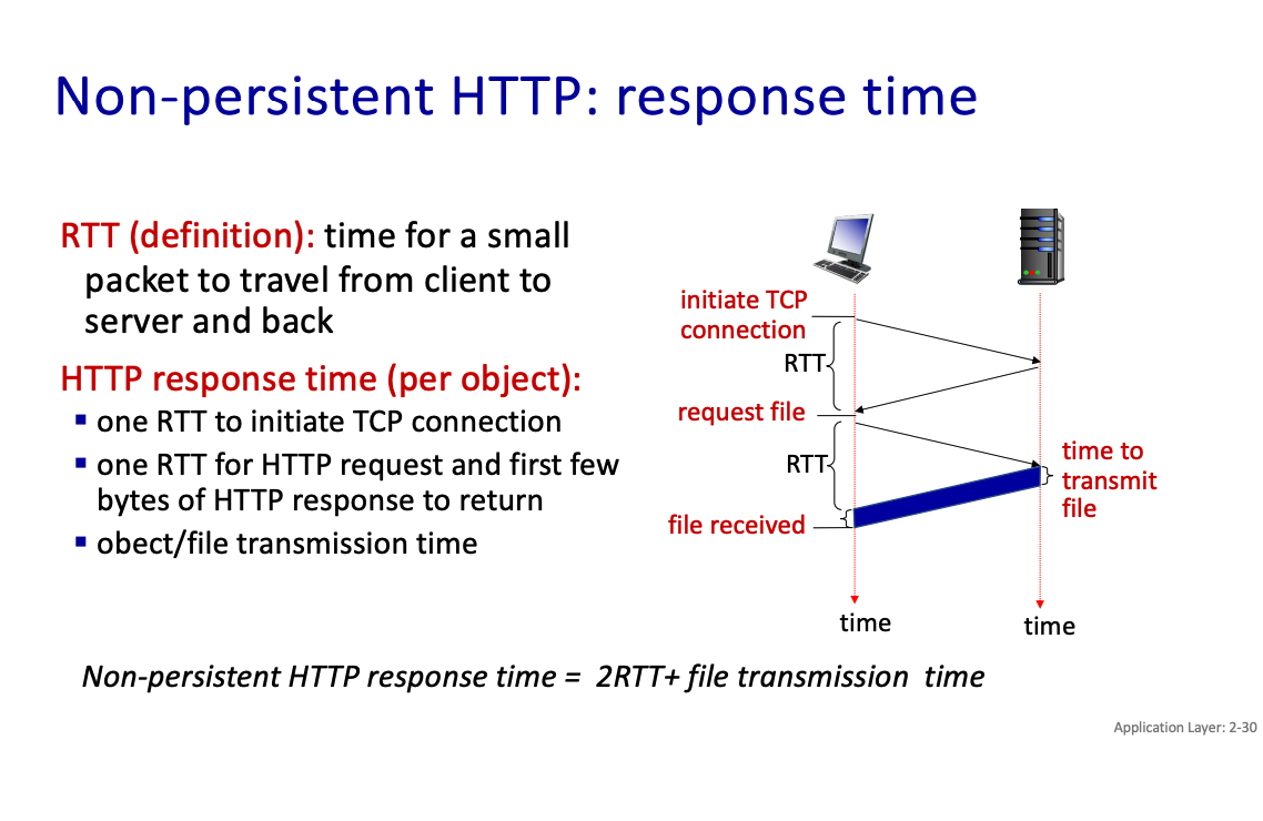
Non-persistent HTTP response time = 2RTT+ file transmission time
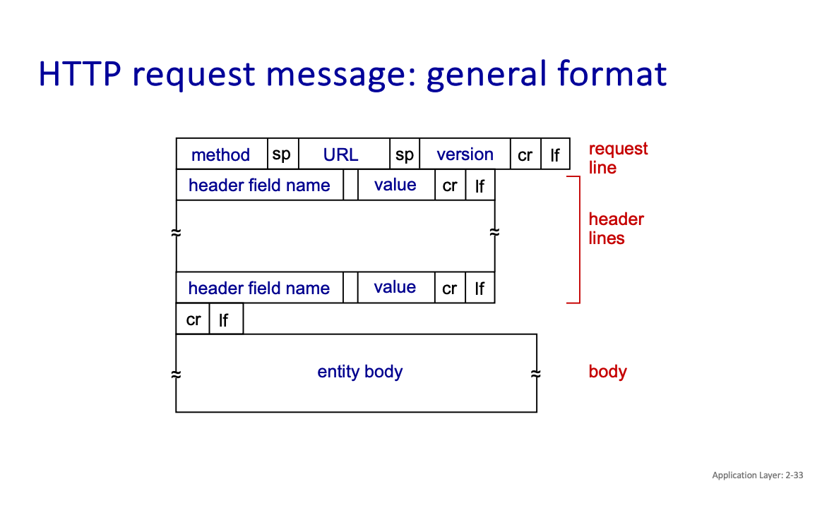
HTTP request message types:
- POST method
- GET method
- HEAD method
- PUT method
Some status codes from HTTP to be aware of: 200 OK
- request succeeded, requested object later in this message 301 Moved Permanently
- requested object moved, new location specified later in this message (in Location: field) 400 Bad Request
- request msg not understood by server 404 Not Found
- requested document not found on this server 505 HTTP Version Not Supported
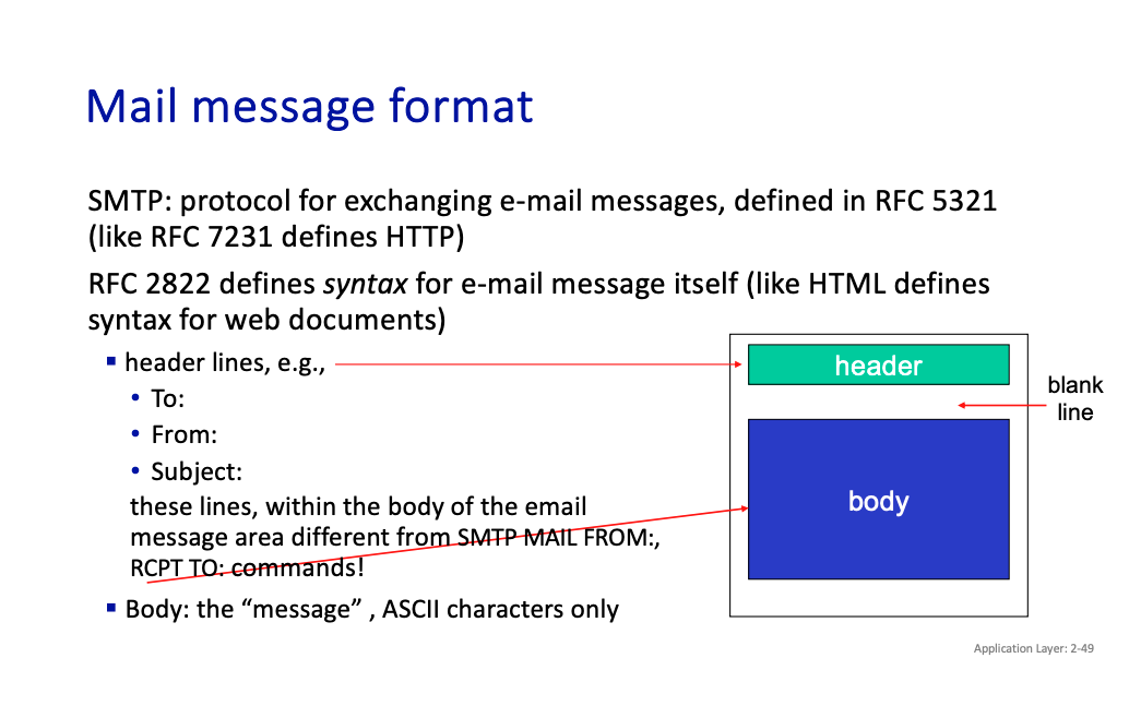
SMTP
comparison with HTTP:
- HTTP: client pull
- SMTP: client push
Both have ASCII command/response interaction, status codes
- HTTP: each object encapsulated in its own response message
- SMTP: multiple objects sent in multipart message
SMTP uses persistent connections
- SMTP requires message (header & body) to be in 7-bit ASCII
- SMTP server uses CRLF.CRLF to determine end of message
DNS
It is a distributed, hierarchical database.
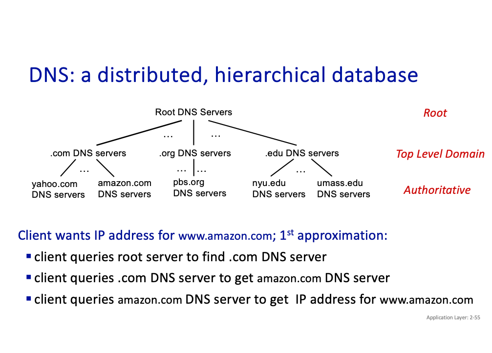
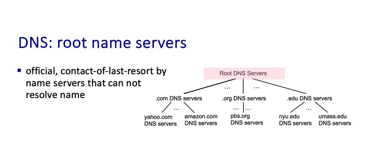
Top-Level Domain (TLD) servers:
- responsible for .com, .org, .net, .edu, .aero, .jobs, .museums, and all top-level country domains, e.g.: .cn, .uk, .fr, .ca, .jp
- authoritative DNS servers
- local DNS servers
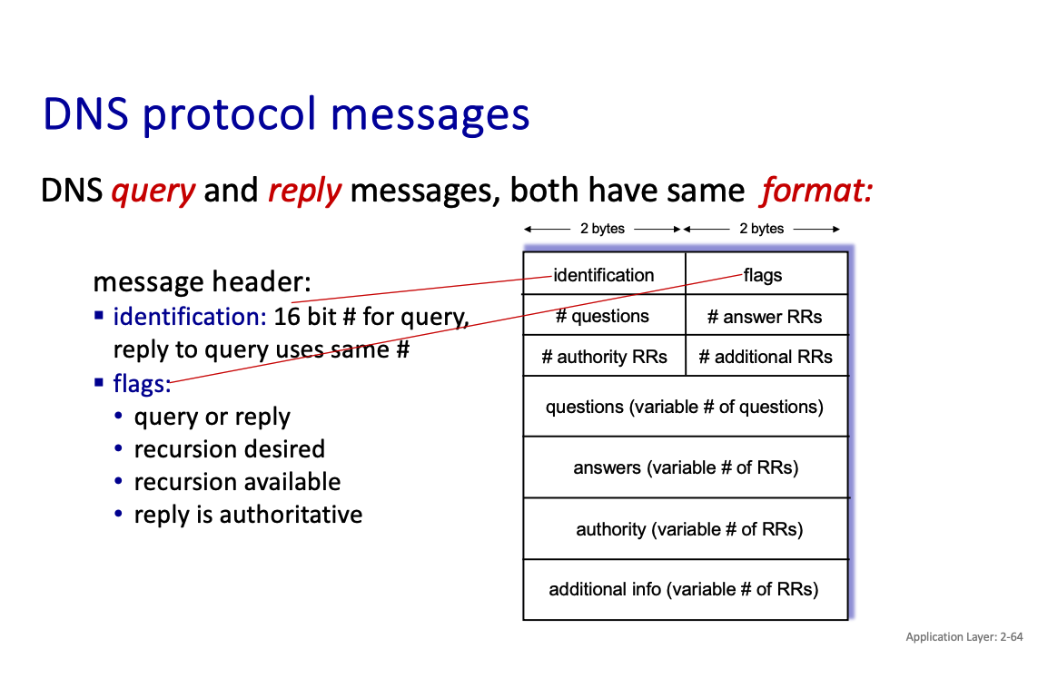
There’s caching.
Chapter 6 : WIFI
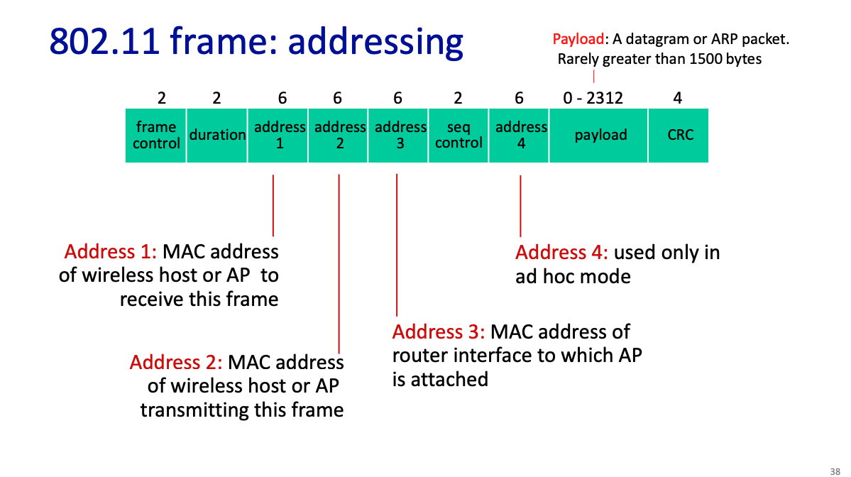
What does a wifi frame look like?
Cellular vs Wi-Fi
- Cellular: wide area coverage, proprietary networks, more coordination between BSs.
- Wi-Fi: local area coverage, “last link” for the Internet, little coordination between APs
- Cellular: licensed (and expensive) spectrum
- Wi-Fi: unlicensed (free) spectrum (2.4 Ghz and 5.3 GHz)
- Cellular: high mobility
- Wi-Fi: low or no mobility
