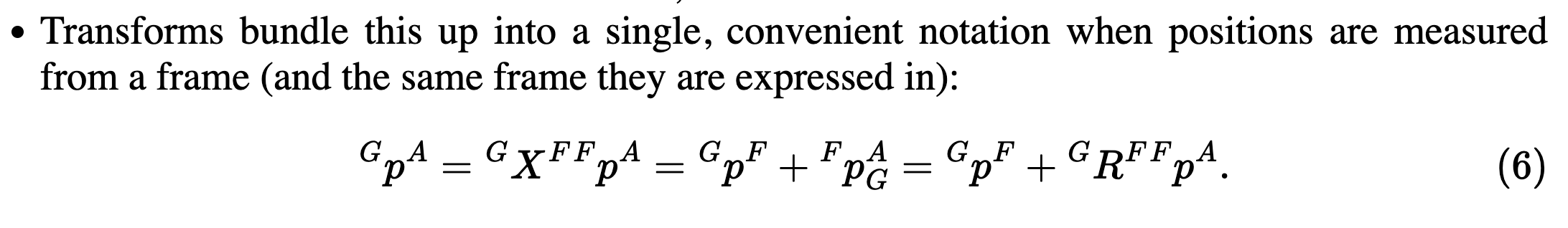
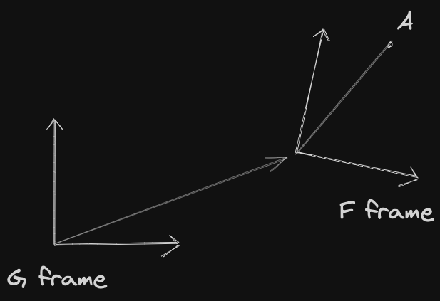
If you want to get the position of A measured from frame G (frame of the gripper), but you measure the position of A from frame F, you can do so by multiplying the point in frame F by the transform between the two frames
The really important thing not to confuse is that you use transform GXF, and not FXG. it takes a bit of time to do some convincing to myself, draw it out
GpA=GXFFpA=GpF+GRFFpA
Now, how is this specifically represented? Is GXF a 3×3 matrix? How does it work?
So the transform includes both translation and rotation. Translation is a 3×1 vector since we simply add a 3D point. The rotation depends on what representation, usually a 3×3 rotation matrix
HOWEVER, we can actually represent GXF as a 4×4 matrix, using the Special Euclidean Group, so that rotation and translation are stored in the same matrix!! And then, you can just multiply matrices together, and write p as a 4×1 vector. More details below
I think I got it!!
the relative distance expressed in different frames does not change the relative distance between two points
Rotation has many common representations, including
Why all these representations? The main issue is Gimbal Lock.
Why all of the representations?
Shouldn’t “roll-pitch-yaw” be enough? Unfortunately, no. The limitation is perhaps most easily seen by looking at the coordinate changes from roll-pitch-yaw to/from a rotation matrix. Any roll-pitch-yaw can be converted to a rotation matrix, but the inverse map has a singularity. In particular, when the pitch angle is 2π, then roll and yaw are now indistinguishable. The physical manifestation of this phenomenon is called Gimbal Lock, where we lose a DOF.
Similarly, the direction of the vector in the axis-angle representation in not uniquely defined when the rotation angle is zero. These singularities become problematic when we start taking derivatives of rotations, for instance when we write the equations of motion. It is now well understood that it requires at least four numbers to properly represent the group of 3D rotations; the unit quaternion is the most common four-element representation.
Also, another issue is like in this case, where you roll first or pitch first produces different output points.
Why don't these issues arise with 2D representations?
Because in 2D, rotation is only around a single axis (the z-axis, the one that comes out of the page towards your face).
Composition of Transforms using SE(3) (Euclidean Transforms)
I was asked this at my NVIDIA interview. I should have known this, but now I know. This is learned from the Visual SLAM book, page 36.
This is slightly different notation than above, because I took it from a different book. At this point, the coordinate frames of each is implied, you should know.
Suppose we made two transformations, R1,t1 and R2,t2. The transform from a to c is
c=R2(R1a+t1)+t2
This is not a super elegant form after multiple transformations. We can introduce Homogeneous Coordinates by simply adding 1 at the end of the 3D vector. Then, we can apply the Rotation and Translation Matrix using the same matrix!!!
Just write down the matrix multiplication. You’ll see that the first row is R×a+t×1=R×a+t=a′, while the second row is 0T×a+1×1=1, so everything works out!
We temporarily use a~ to represent the homogeneous coordinates of a. Then, relying on homogeneous coordinates and transformation matrices, the superposition of the two transformations can have a good form:
b~=T1a~,c~=T2b~⇒c~=T2T1a~
Back to the Drake (Robot) notation, this is how you can compose transforms by having
AXBBXC=AXC
To use the Euclidean Transformation in Eigen, we use Isometry3d. There are several ways to initialize:
Isometry3d T = Isometry3d::Identity(); Isometry3d T(q); // IMPORTANT: q must be a UNIT quaterionIsometry3d T(rotation_matrix);Isometry3d T; // garbage values
Rotation and translation
// MAKE SURE T is intialized to Identity()T.rotate(rotation_vector); // Accepts Quateriond, AngleAxisd, or Matrix3dT.pretranslate(Vector3d(1,3,4)); /*Tranform matrix = 0.707 -0.707 0 1 0.707 0.707 0 3 0 0 1 4 0 0 0 1*/
IMPORTANT: Under the hood, what actually is happening is doing a matrix multiplication, instead of writing to the entries, which is slower
To apply the transformation, we simply multiply
Vector3d v_transformed = T * v; // Equivalent to R * v + t
Composition of transformations
Isometry3d T1;Isometry3d T2;// Set T1 and T2 to correct values...// Then, composition of transforms is done like thisT2 * T1 * Vector3d(1,2,3);
Actually, we work work with these transformations (rotation and translation), everything is done through matrix multiplication of 4×4 matrices. Yes, even translation. This makes the code run a lot faster.
Rotate, then Translate
I heard this before but was not convinced. This stackexchange post really helps.
Remember that when you call translate(), this is actually implemented through a matrix multiplication. If you then call rotate(), this calls rotate on the translated point, which would be INCORRECT.
So when you have GpA=GpF+GRFFpA, in my mind, I’m “translating first, then rotating”, but no, you are applying the rotation first to the point, then translating. Also see Change of Basis.
Rule of Thumb
My rule of thumb is to always use pretranslate and rotate as I learned from the Visual SLAM book. Only use these functions to set the initial values of the Isometry3d matrix. Then, composition of transforms should be done by doing something like T2 * T1.
Ahh I see why they do this. If you always call pretranslate and rotate, then you are less prone to mistakes. This is clearer with the example below
If you do prerotate and pretranslate, you are prone to mistakes. You need to call prerotate first
Example where it breaks down if you don’t respect this:
Isometry3d T = Isometry3d::Identity();Vector3d translation(2,5,5);Matrix3d rotation_matrix = Quaterniond(1, 0.2,0.4,0.2).toRotationMatrix();/* 0.6 -0.24 0.88 0.56 0.84 -0.24-0.72 0.56 0.6*/// GOODT.rotate(rotation_matrix);T.pretranslate(translation);/* T= 0.6 -0.24 0.88 2 0.56 0.84 -0.24 5-0.72 0.56 0.6 5 0 0 0 1*/// BADIsometry3d T2 = Isometry3d::Identity();T2.prerotate(rotation_matrix);T2.translate(translation);/* 0.6 -0.24 0.88 4.4 0.56 0.84 -0.24 4.12-0.72 0.56 0.6 4.36 0 0 0 1*/// WORKS too, but You gotta BE SUPER CAREFUL TO CALL ROTATION FIRSTIsometry3d T3 = Isometry3d::Identity();T3.prerotate(rotation_matrix);T3.pretranslate(translation);/* T= 0.6 -0.24 0.88 2 0.56 0.84 -0.24 5-0.72 0.56 0.6 5 0 0 0 1*/// WORKS, don't need to worry about which to call firstIsometry3d T4 = Isometry3d::Identity();T4.pretranslate(translation);T4.rotate(rotation_matrix);