SLAM

Visual SLAM

Uses cameras to construct a map of the environment. Does feature matching, see ORB-SLAM Read up on the book: https://github.com/gaoxiang12/slambook-en/blob/master/slambook-en.pdf

  • Available locally file:///Users/stevengong/My%20Drive/Books/Coding/slambook-en.pdf

Tesla kind of does SLAM by creating a bird-eyes view from multiple camera views.

Watch this: https://www.youtube.com/watch?v=saVZtgPyyJQ

https://www.kudan.io/blog/camera-basics-visual-slam/

Other resources:

You basically try to figure out where the features align.

Implementation

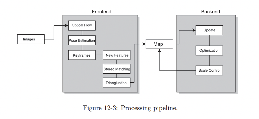
Classical Visual SLAM Stack
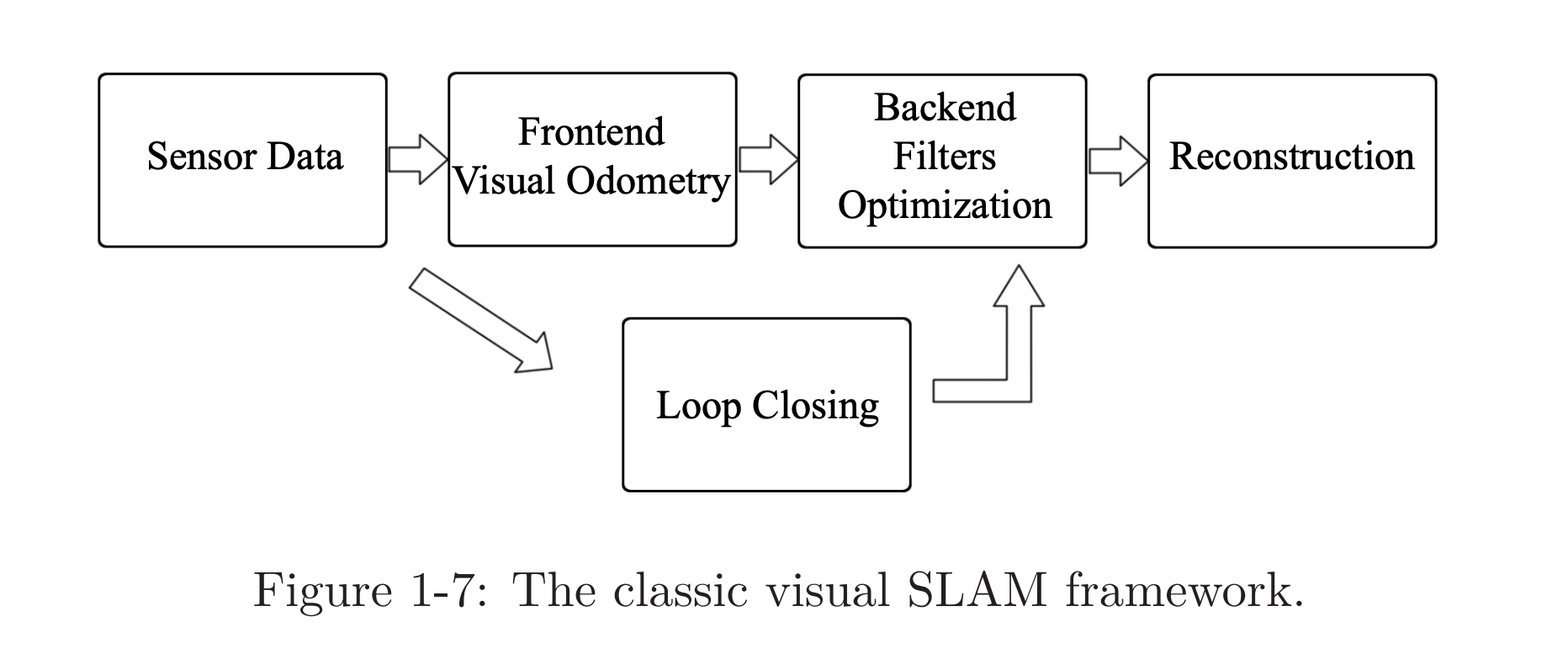
A typical visual SLAM workflow includes the following steps:

  1. Sensor data acquisition. In visual SLAM, this mainly refers to for acquisition and preprocessing of camera images. For a mobile robot, this will also include the acquisition and synchronization with motor encoders, IMU sensors, etc.
  2. Visual Odometry: VO’s task is to estimate the camera movement between adjacent frames (ego-motion) and generate a rough local map. VO is also known as the frontend.
  3. Backend filtering/optimization. The backend receives camera poses at different time stamps from VO and results from loop closing, and then applies optimization to generate a fully optimized trajectory and map. Because it is connected after the VO, it is also known as the backend.
  4. Loop Closing. Loop closing determines whether the robot has returned to its previous position in order to reduce the accumulated drift. If a loop is detected, it will provide information to the backend for further optimization.
  5. Reconstruction. It constructs a task-specific map based on the estimated camera trajectory.

frontend more relevant to computer vision topics (image feature extraction and matching) backend state estimation research area

Formalizing

Context

The formalization below will be a little abstract, so here is some more context.

  • There are discrete timesteps , at which data sampling happens
  • We use to indicate positions of the robot, so the positions at different time steps can be written as (the trajectory of robot)
  • The map is made up of several landmarks, and at each time step, the sensors can see a part of the landmarks and record their observations. Assume there is a total of landmarks in the map, and we will use to denote the landmarks.

The are just high level abstract formalizations, see page 17.

Motion Equation (this is like the controller, can be obtained from IMU) where

  • is position at timestep
  • is the input commands
  • is noise

Observation equation (this comes from the camera)

where

  • is observation data
  • is a landmark point at
  • is the noise in this observation

confusion

This abstract equation is kind of confusing. We don’t have usually, nor , I don’t get the point of this equation. The motion equation is much more straightforward. To revisit.

β€œthe robot sees a landmark point at and generates an observation data ”

These two equations together describe a basic SLAM problem: how to solve the estimate (localization) and (mapping) problem with the noisy control input and the sensor reading data?

Now, as we see, we have modelled the SLAM problem as a State Estimation problem: How to estimate the internal, hidden state variables through the noisy measurement data?

Example

Depending on the actual motion and the type of sensor, there are several kinds of parameterization methods. What is parameterization?

Motion equation example For example, suppose our robot moves in a plane, then its pose is described by two coordinates and an angle, i.e., , where are positions on two axes and is the angle. At the same time, the input command is the position and angle change between the time interval: , so the motion equation can be parameterized as:

{\left[ \begin{array}{l} x_1\\ x_2\\ \theta \end{array} \right]_k} = {\left[ \begin{array}{l} x_1\\ x_2\\ \theta \end{array} \right]_{k - 1}} + {\left[ \begin{array}{l} \Delta x_1\\ \Delta x_2\\ \Delta \theta \end{array} \right]_k} + {\mathbf{w}_k}, \end{equation}$$ where $\mathbf{w}_k$ is the noise again. This is a simple linear relationship. However, not all input commands are position and angular changes. For example, the input of "throttle" or "joystick" is the speed or acceleration, so there are other forms of more complex motion equations. At that time, we would say the kinematic analysis is required. **Observation equation** example Imagine that the robot carries a two-dimensional laser sensor. We know that a laser observes a 2D landmark by measuring two quantities: the distance $r$ between the landmark point and the robot, and the angle $\phi$. Let's say the landmark is at $\mathbf{y}_j = [y_1, y_2]_j^\mathrm{T}$, the pose is $\mathbf{x}_k=[x_1,x_2]_k^\mathrm{T}$, and the observed data is $\mathbf{z}_{k,j} = [r_{k,j}, \phi_{k,j}]^\mathrm{T}$, then the observation equation is written as: $$\begin{equation} \left[ \begin{array}{l} r_{k,j}\\ \phi_{k,j} \end{array} \right] = \left[ \begin{array}{l} \sqrt {{{\left(y_{1,j} - x_{1,k} \right)}^2} + {{\left( {{y_{2,j}} - x_{2,k} } \right)}^2}} \\ \arctan \left( \frac{{y_{2,j}} - x_{2,k}}{{y_{1,j} - x_{1,k}}} \right) \end{array} \right] + \mathbf{v}_{k, j}. \end{equation}$$ When considering visual SLAM, the sensor is a camera, then the observation equation is a process like "getting the pixels in the image of the landmarks." #### Other I think [[notes/Sachin|Sachin]] showed me this image instead ![[attachments/Screenshot 2023-10-21 at 9.47.14 PM.png]]