Raceline Optimization
The racing line is the optimal path around a racetrack. We can solve for this theoretical optimal racing line by doing raceline optimization. I do this on a frequent basis to plan a racing trajectory for the F1TENTH. Referenced in my F1TENTH Field Usage.
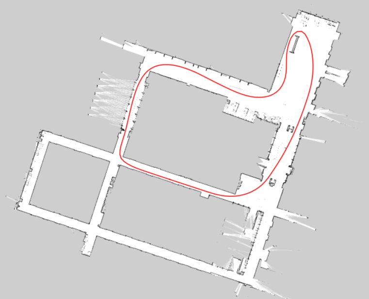 An example of a raceline that I’ve generated in E7.
Repositories
- TUMFTM/global_racetrajectory_optimization (~2 mins to generate if you get your parameters right)
- BayesRace takes too long to generate (~1 hour to generate)
Great videos to better understand racelines
- All about corners - F1 explained
- Racing Lines explained
- Why the Racing Line Doesn’t Win Races
- The Racing Line - 4 Elements of a Perfect Corner (Physics Explained + Sim Training Tutorial & Tips)
- F1TENTH Raceline Optimization Slides
- Physics of Racing
Why is this problem is hard?
You can’t talk about racing lines also depend on the racing condition and tire condition, and also when you battle with another driver
- Great video Chris Gerdes (Stanford): Lessons for Autonomous Racing
- “Difference with expert driver” 1% better at everything
- “You can’t drive at the absolute friction limits and follow a path”
- Need to know Dynamics of vehicle and track conditions
- Sim2Real problem
- Track conditions change every day, how can you have your car learn in real-time, integrate some sort of feedback loop, to avoid crashing?
- Balance oversteer and understeer
The Process of Generating Racelines
My Implementation for F1TENTH can be found in CL2-Uwaterloo/Raceline-Optimization.
Here are the high level steps to generate a racing line:
- Generate a map using
slam_toolbox - Edit the map into a racetrack using a tool like Photoshop
- Generate centerlines + track widths from the map
- Run optimization to generate the racing line
The final racing line will be specified in a .csv file, where each row contains a tuple of values, specifying the target -positions and the velocity to drive the racing car at for these positions.
1. Generate a Map using slam_toolbox
To generate a raceline, you first need to a track to optimize on. We use slam_toolbox to generate an Occupancy Grid map, where
- black pixel = “occupied cell, i.e. walls”
- white pixel = “free cell”
- gray pixel = “unknown cell”
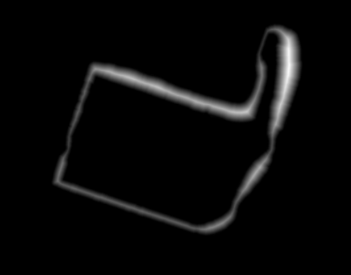
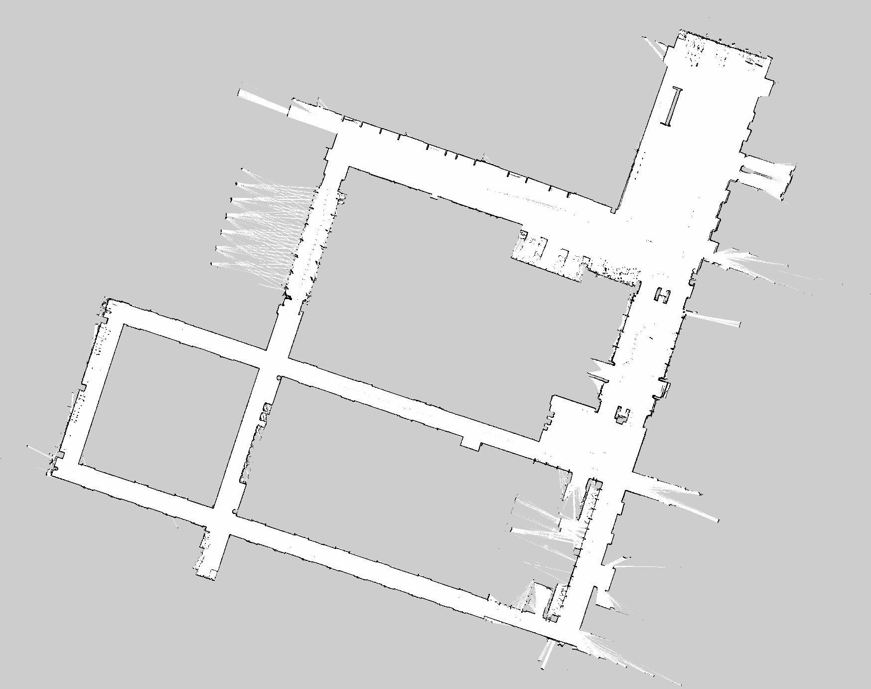 Example of map generated in
 slam_toolbox.
Output from slam_toolbox:
<MAP_NAME>.pgm: The actual map image. The.pgmmeans that it is in grayscale<MAP_NAME>.yaml: specifies the origin and well as the resolution (pixel / m) of the image, so we can go from an image (pixel) Reference Frame to the world reference frame.
Example of a .yaml file:
image: Spielberg_map.png
resolution: 0.05796
origin: [-84.85359914210505,-36.30299725862132, 0.000000]
negate: 0
occupied_thresh: 0.45
free_thresh: 0.196
2. Edit the map into a racetrack using a tool like Photoshop
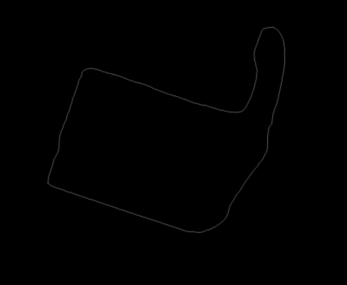
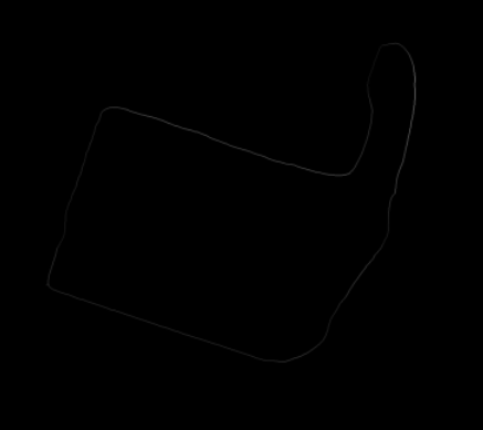
The map above is open. We need to clean it up and turn it into a closed racetrack, so we can generate centerlines afterwards. In my case, I just use Photoshop to convert the original map into a closed racetrack.
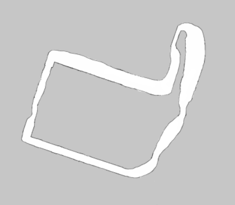 Example of map after editing with Photoshop.
Tips on how to clean map for a nice racetrack
In general, here are the recommendations so that the next step (extracting centerline works well):
- Smooth walls
- Remove any noise. Dynamic obstacles or black dots on the map.
If it’s a very large map, to make the process faster, you don’t need to draw the black edges. Just use white for the driveable area. My script in the next step should take care of that.
3. Generate a reference line (centerline) from the map image
The raceline optimizer uses a different representation of the racetrack in order to find the optimal raceline: we need to represent the racetrack in terms of the centerline and track widths. Specifically, we need the following values:
- = given centerline point on track
- = distance to the left boundary
- = distance to the right boundary
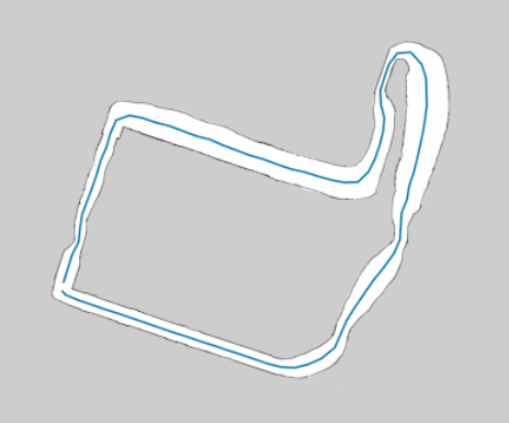
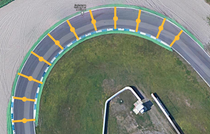 The yellow point and line in this image is the track representation that we need to extract.
Since we are extracting the centerline, and should have the same values.
Once we have this representation, we can then connect these centerline points using a cubic Spline, and run optimization on it.
Use the map_converter.ipynb script to extract these racing lines.
The Underlying Algorithm to generate Centerline (Reference Line)
I actually spent quite a bit of time trying to refine this algorithm. At first, I came up with trying to extract the left and right edges of the track boundaries, and using the midpoint between those edges. However, this fails spectacularly as the track gets larger (which two left and right point do you associate?). Then, while searching for better solutions, I found the F1TENTH slides, and this paper (page 33), where they talk about using Euclidean Distance Transform + Watershed Algorithm. That is where EDT idea came from, but I don’t know how they successfully used the watershed algorithm to extract a centerline (did not work for me). If anyone knows, shoot me a message.
My current centerline extraction algorithm has the following steps:
- Compute Euclidean Distance Transform (EDT) for the image
- Threshold the EDT image, and apply the Skeletonize function on the thresholded image to get a 1 pixel width line
- Use the skeletonized image to mask the EDT image, each pixel that has a value will represent the track width at that particular point
- Run DFS to extract the coordinates of the pixels, along with the track width
- Use the
.yamlfile to transform from pixel frame to world frame (in meters).- Export into a
.csvfile, where each row is(x_coordinate,y_coordinate, right_track_width, left_track_width)
 The centerline overlaid on top of the original map.
4. Run optimization to generate the racing line
There are multiple ways to formalize the optimal raceline problem (Shortest Possible Path, Minimum Curvature problem, or Minimal Time Problem). My repository has solvers for all three, but I currently use the mintime implementation.
At a high level, the optimization algorithm takes in the reference line (centerline), and tries to adjust it in a way that maximizes the vehicle’s average speed, while staying within the constraints of the vehicle and track.
- The optimization process involves iteratively adjusting the path until convergence
The main script to generate a raceline for the F1TENTH can be found in main_globaltraj_f110.py. To generate the racing line, change the MAP_NAME and simply run
python main_globaltraj_f110.pyConfiguring parameters
For the F1TENTH, I’ve custom configured the f110.ini file, which specifies the parameters.
The most important parameter to configure is the friction. If you are on a super slippery track like myself, then the friction is to be set pretty low. In my case, like 0.4.
"mue": 0.4
Friction
- Asphalt: 0.6 - 0.9
- Concrete: 0.5 - 0.8
- Rubberized tracks: 0.9 - 1.1
- Gravel: 0.4 - 0.8
- Grass: 0.2 - 0.4
- Sand: 0.1 - 0.3
To increase or decrease the safety margin (how close do you want to race to the walls), change the width_opt parameter:
optim_opts_mintime={"width_opt": 0.9,
					...
				    }
If the optimization is taking too long, you will need to increase the step sizes:
stepsize_opts={"stepsize_prep": 0.05,
"stepsize_reg": 0.15,
"stepsize_interp_after_opt": 0.1}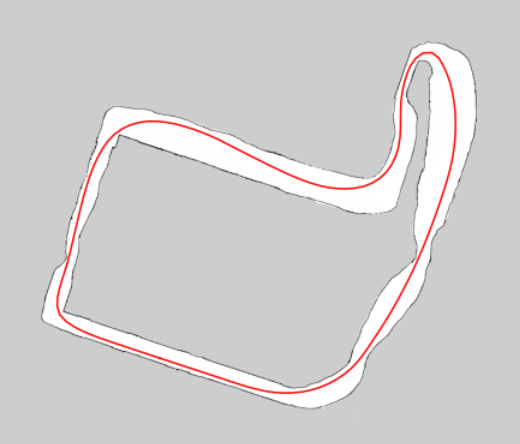 The final raceline visualized, generated using my visualize_raceline.ipynb notebook.
The final racing line is given in a .csv file, where each row contains a tuple of values, specifying the target -positions and the velocity to drive the racing car at for these positions.
-10.6600935,0.8222625,7.8270057
-9.7119030,0.5087592,8.0844664
-8.7649168,0.1964836,8.3324815
-7.8177234,-0.1157373,8.5709665
-6.8705507,-0.4279334,8.7926030
-5.9236689,-0.7398376,9.0056199
-4.9751331,-1.0524731,9.2105343
-4.0292445,-1.3647249,9.4009872
-3.0828317,-1.6756690,9.5524947
-2.1301531,-1.9831352,9.6676858
...
Raceline Optimization Notes
When we run optimization, we are actually interested in doing trajectory planning as opposed to Path Planning
- Path planning spatial domain
- Trajectory planning spatial-temporal domain
There are 3 types of optimality:
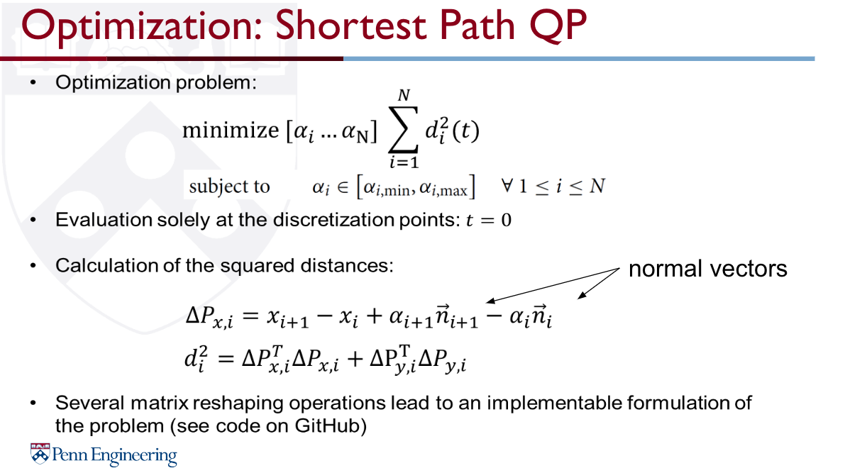
- Shortest Possible Path (geometric QP)
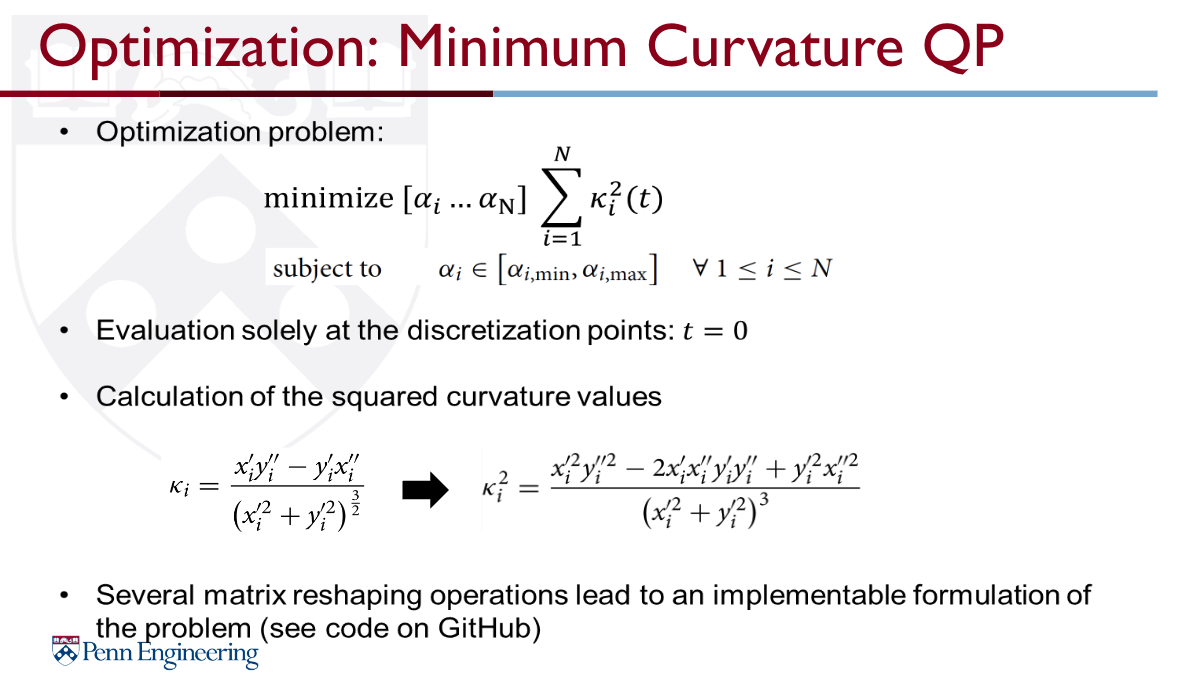
- Minimum Curvature problem (geometric QP)
- Minimal Time Problem (Optimal Control)
Shortest Path
Minimum Curvature
We solve minimum curvature problem by decoupling our problem into 2 parts:
- Path Planning (geometric QP)
- Velocity Planning
 Typical solver types for planning a velocity profile on the race track
- Quasi-steady state solvers → Forward-Backward Solver
- Optimization → SpeedOpt
Minimum Time Problem
How to optimize to speed? See F1TENTH 2020 Lecture →
There are two ways:
- Convex Optimization
- This has essentially been solved through the “Minimum-time speed optimization over a fixed path” in 2014.
- You need to model the dynamics of the vehicle
- Genetic Algorithm
The thing is, not only do you want a raceline, but you also want the velocity associated with it.
The repo for example, only contains code for generating the raceline:
Personal Notes
Dividing the racetrack into segments and using collocation points within each segment helps us break down the problem into smaller, more manageable pieces and allows us to find an optimal solution to the overall problem.
https://www.youtube.com/watch?v=wlkRYMVUZTs&t=461s
We optimize with respect to 5 state variables:
- Velocity
- Side Slip Angle
- Yaw Rate
- Lateral Distance
- Relative Angle
There are also 4 control variables
They use the Double Track Model to solve it.